Showing posts with label Laser Cutting. Show all posts

Thursday, 27 November 2014

SLA 3D Printer Project Log 11: Lasing on a sunny afternoon...

Exciting news on the making front:  my Laser Cuts have arrived!  Before I've even finished cutting my Extrusions (I'm a horrendous procrastinator), CutLaserCut of London have furnished me with 6mm Plywood Panels for the exterior; These parts have an almost psychotic precision to them - I drew these in Sketchup which draws Circles as slightly smooth polygons, and every face was sharply defined on even the smallest curves, running my finger over them felt like a D20 would if you felt it with your foot.

I reckon on a little show 'n' tell:

Clockwise from left:  Rear panel with PC Case and 180mm fan in place, Top Panel, Bottom Panel.
As you can see I stuck to fairly simple shapes for this, with lots of holes for the M4 bolts holding the panels on.

Left:  Front Panel; Right:  Both Side Panels (they're identical)
The Oblong bevelled holes are for the access panels which are to be made out of Fluorescent Acrylic (these absorb UV light, cuts out light pollution from external sources).

Another shot of the rear panel with rear-mounted equipment in place.
Of course, the fans will be internal and behind fan grilles once I assemble this thing, but the PC will remain external for access and cooling.

Misc Accessories, parts which make up things like the build bed (bottom left) and the Z carriage upper plate (top right).
The only problem I can see so far is the fact that many of the panels have warped, as can be expected for such thin plywood panels of this size.  It doesn't matter for parts other than the Z Carriage and possibly the Top Vent Cover (the rectangular plate with curved corners and all the cut-outs in), so I think I'll use Aluminium Angle bolted to the Carriage to ensure a level fixture for the Bearings and Threaded Rods driving the Z Carriage up and down.

"Why not use more plywood, or just glue on some Straight Scrap wood?"  Wood has a fantastic Strength-Weight ratio, especially Plywood, but ultimately while it can be very stiff, it is not that strong overall; The parts I use to stiffen can also warp which takes me back to my original problem.

Whew, an enticing delivery indeed, a glimpse into the future form of my Printer; just to end it on a high note, let us view this ultra-cute image of my bodged projector perched on it's mounting plate:

So far I've logged more hours watching youtube videos on this thing than it would be used for roughly 100 small prints!
Stay Industrious.

Sunday, 29 June 2014

SLA 3D Printer Project Log 9: Call me tight-fisted...

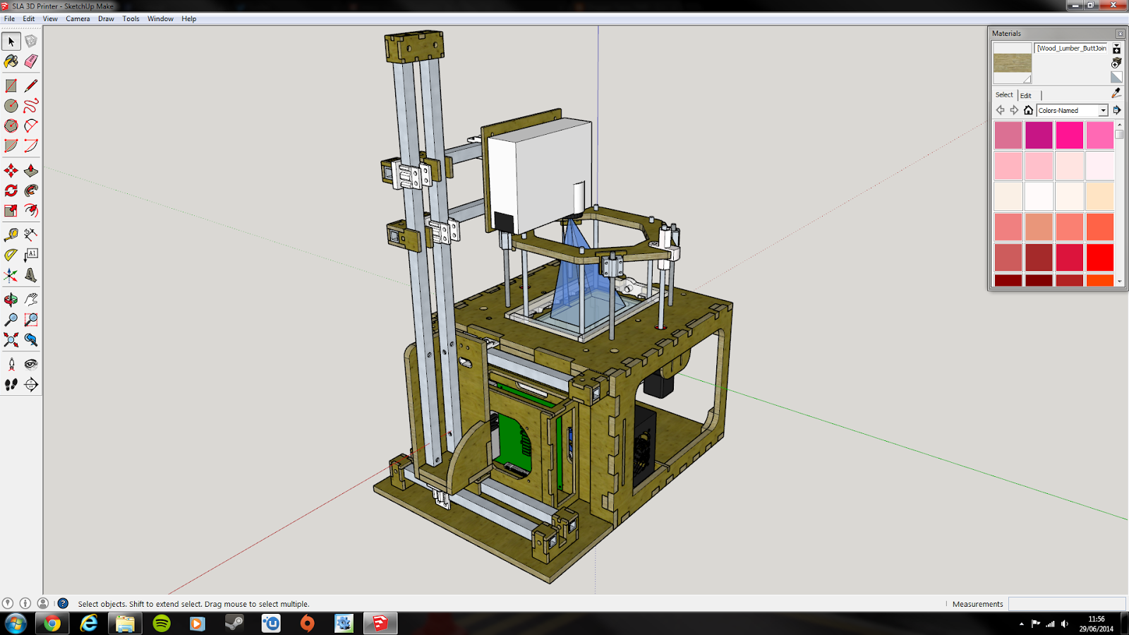
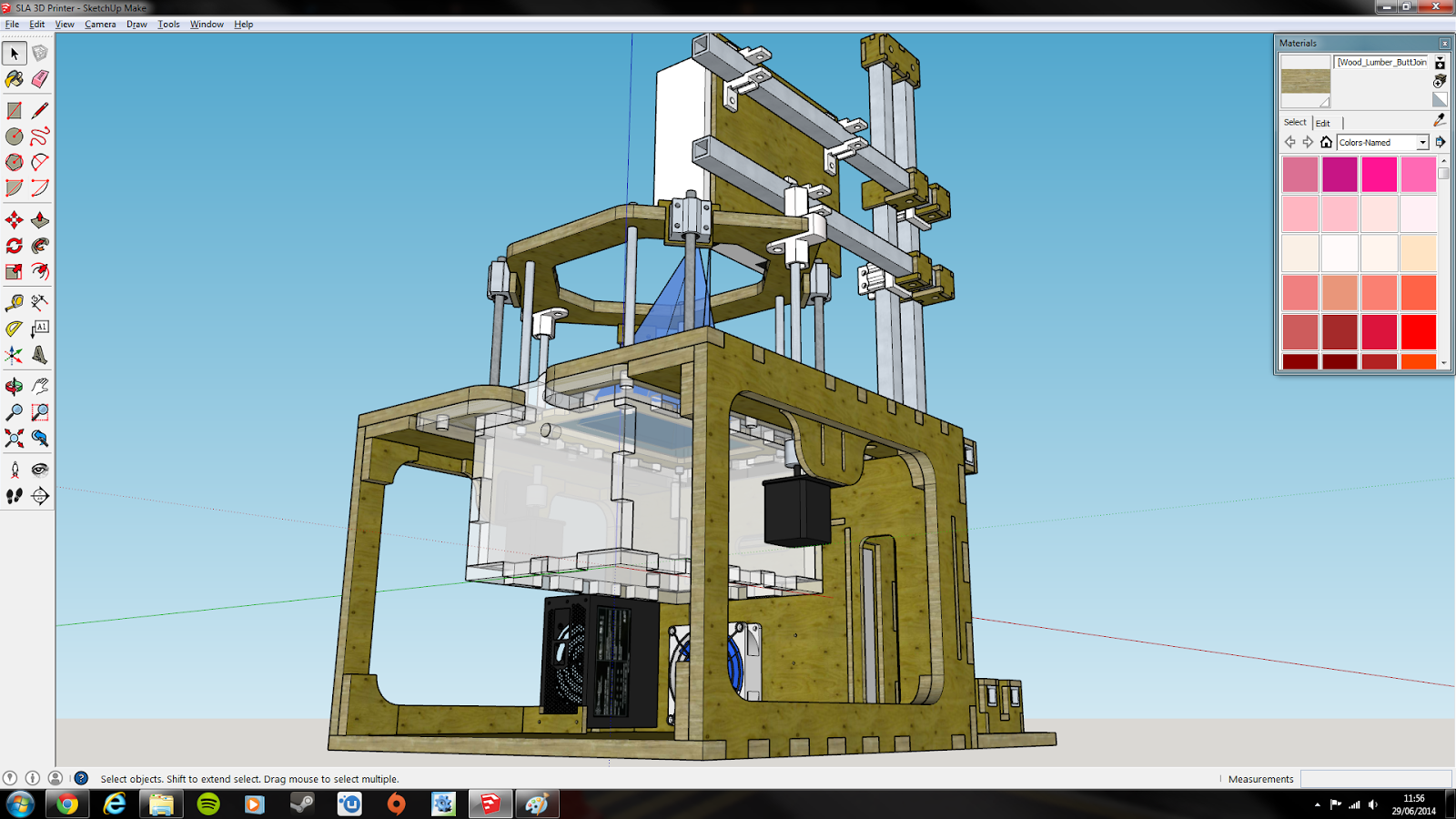
Been almost a god-forsaken month since I last posted on this!  Usual excuses apply - work, tiredness and other priorities.  Regardless of this, I am proud to present a completed model for the SLA 3D Printer!

Mostly Plywood construction to keep 3D Printing costs in check.
As much as I'm tempted to excuse the lack of RAMPs Board and some of the hardware (nuts, for instance), the simple fact is that I couldn't be bothered...
This is where the action is - looking down on the print bed with the beam set to 12.8 x 8.0 cm build area.
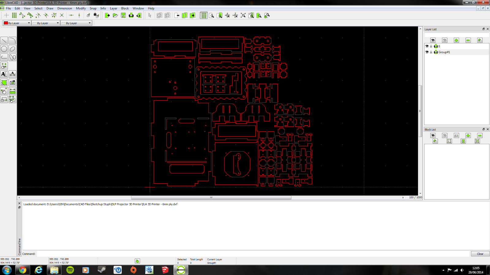
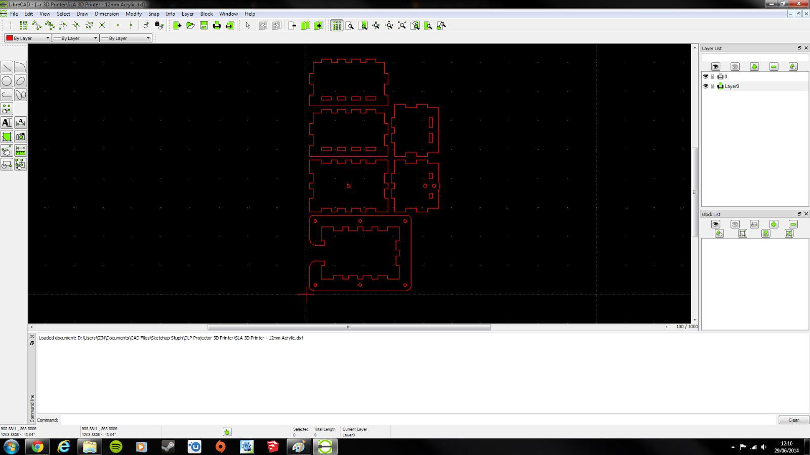
With this simple design in mind, let me take you through the DXF files for the laser cutting, which should hopefully let you know just how much goes into things like this:
25346.8mm of lasering goes into the 6mm ply parts ALONE.
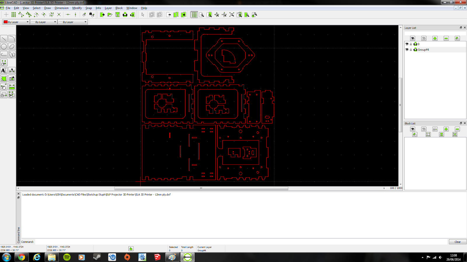
Looks refreshingly simpler, but these 12mm ply parts still need 25260.6mm of cutting.
Finally, 12mm Cast Acrylic makes up the basin with a mere 8290.95mm of cuts.
Some of you may be thinking "Gee, that's sure to be expensive with all those finger joints and details" - how does £400 inc VAT sound?  Sure, it's a major expense, but would *you* consider doing this by hand?  All I need to do is persuade my ego to let go of that 4K monitor for just a few more months (not gonna happen ;) )

If you've read this post over at the life blog (to hell with re-writing the name here, that pubescent cacophony of letters needs to change), you may notice that I am aiming for change in the coming months not just with my blogs but my whole life - things are getting quite heavy for me and I need to re-tool.  The basic gist is that I am trying to do too much and it's driving me insane to the point where I just dive into PC Gaming and get nothing done, so a few things may have to come and go.  This project is here to stay (why not cut out the middleman for minor detail/operation changes?), but I'm looking into other avenues to try my hand that may eventually make me a decent living if I can pull it off correctly.

Finally, all my blogging is now on here, (pubescent jumble blog) is now mothballed.  Hope to see grasshopper-minded adventures on a much grander scale once this bridge is crossed.

Stay Industrious...

Saturday, 3 May 2014

SLA 3D Printer Project Log 7: Underframes? Thought I did those in Creo...

I've been working on underframes, I know, it's a bit soon to resume work on the wagons but I'm on about the mounting system for my 3D printer; until now I had components floating in space - not an ideal proposition for accuracy.  That has now been fixed, and I was in for some wake-up calls.

Don't worry, there'll be 10mm bolts holding the basin in place.
The dimensions were envisioned as a worst-case scenario of 1m3, which would give me plenty of wiggle room to add insane features like gull-wing doors and water-cooling for the built-in pc, but the dimensions as they stand now are 412mm x 380mm x 626mm.  I reckon I can now aim for a desktop model, and this means a few changes:

  • I'll probably ditch the case, and just use a black cover when not in use to prevent the resin from curing - this will probably save me a lot of bother when maintaining my printer.
  • A Mini-ITX PC is essential - I can no longer use the bulk of the unit to house an ATX motherboard.
  • Get more sensible with the design - I (and possibly you) am going to use this printer frequently, I need something serviceable.
  • Mounting the touchscreen just got a lot harder...

A few ancillary developments have happened in my life recently; I've got a new job at a composite manufacturer running cure checks for them, and one of the things I observed is that the Autoclaves run standard PCs alongside their massive built-in computers to run the UI; maybe I shouldn't follow the leader, so to say, but it gives me reassurance that my plan to use an x86 PC to control this thing isn't insane after all.

As much promise as the Pi had, I am not a coder, and Raspbian didn't run how you'd call slick (Risc OS did, but it doesn't support wireless internet which makes things a hell of a lot harder these days); if I'm going to use it everyday, which I may do for a few weeks of each quarter, I'd prefer a rapid system as well as one which has a GUI.

I intend to install Windows 7 Basic to run Creation Workshop by PacManFan, a program which can slice the STLs as well as operate the printer with the help of RAMPS board.  This program uses little CPU power, so the Pentium E2160 I possess can be used (I bought it for a secondary gaming rig, to use whilst home from University), but it does use a lot of GPU power in it's Model View, which runs on OpenGL; I bring up OpenGL because it means that Workstation Cards, designed largely for OpenGL-accelerated CAD programs, could give stellar performance.

I'll expand upon this further when the time comes, I'm getting tired in one of my few windows of time I have to do CAD and blog, in spite of the much-needed money.

Regards.

Tuesday, 1 April 2014

SLA 3D Printer Project Log 4: A projector mount with traversing features, potential as a garden railway traverse table?

Aside from experiments in salt, I have been working on a mounting method for my projector; one which offers versatility both in terms of adjusting projector distance to vary the build area/resolution balance and also to make way for projector upgrades.  Given that I am building a top-down design this is no easy task considering that gravity threatens to either collapse my construction or slowly inch the projector down and out of focus.  So far, this is my design which as of yet only features the vertical axis:
Looks very Reprappish, and that's because it is :D
I am keeping to Reprap parts as much as possible since every 3D printing enthusiast and their Budgie has a Prusa Mendel of some kind, so relevant parts will be cheaper; the central rod is a M8 threaded rod and the other two are 8mm plain steel rods for support and guidance, SCS8UU bearings are used throughout due to their cast metal housing and built-in M4 threads.  Another thing to note is that the Traverse Plate (highlighted in green) is not what will carry the projector - I intend to make another plate bespoke to the mounting requirements of my projector and users can make bespoke mounting plates for their respective projectors.
The bearings for the horizontal guide rods can clearly be seen.
The Backplate may look a bit skeletal for some, but this is made out of 12mm plywood; 6mm plywood may be used to allow for simplification of manufacture with other parts like the Traverse Plate, with 12mm parts made of two 6mm parts epoxied together (this also allows for half-engraved features without half-engraving, which could bring potential de-lamination issues to a single 12mm sheet).  The large amount of space also allows for a high degree of nesting to occur, saving material and space on the laser bed.
Trusses added for stylistic reasons ;)
This is the mounting cross for the Traverse Plate, where the plate interacts with the M8 rod to allow the plate to move vertically; this is done via two M8 nuts located in slots (just visible above), of which one or both may be a nylock nut to provide friction when traversing is not required.  This is made from a 12mm (or 2 x 6mm) plywood cross which interfaces with a 3D printed nut mount to create the mounting cross.
Reprap inspiration is found again...
Finally, we have the clasps for the plain steel rods that guide the Traverse Plate.  Not much to mention here other than it's 3D printed, I've decided to use Shapeways for my prints since it's WSF printers offer almost infinite flexibility in the shape of my objects within reason and my Reprap is giving me constant trouble right now, so much for saving money by printing at home :(

Good news is that design should be straightforward from here, since I only need to replicate the parts I have made here in the horizontal axis with a few minor tweaks.  Pity this is only one of five sub-assemblies I am slated to design (Projector Mount, Resin Basin, Z axis with build plate, the Mounting Frame and the Case).