Showing posts with label 3D Printing. Show all posts

Friday, 6 March 2015

Lee Moor, 2nd of her name

Tawe TMD's Shapeways Page.  Looks pretty barren, does it not? I reckon it's about time I did something to rectify that.

For whom it concerns, yes, the SLA 3D Printer Project is still underway, painting is taking a lot longer than expected, even with the convenience of aerosols.  The good news is that allows me to take on a new, shorter project while this one pans out. Looking over the Hornby L&Y Pug I reviewed last time, I began to have an epiphany – the harder I looked at it, and the Lee Moor Tank Engines, the more convinced I became that I had a perfect beginner's kitbash on my hands!

Behold!

Hope comes to me in the form of The Lee Moor Tramway: A Pictorial Record by Roy E. Taylor. This is a collection of photographs, mostly from 1900 onwards, of the tramway in operation; diagrams of the Lee Moor Locomotives, perchance? Sadly not. I'll probably find more use for this material when I get round to building a layout on the subject, for in terms of the line itself, it's an unbeatable resource. It's also an invaluable authority on the details present on the Locomotives themselves – I now know that they carried screw jacks aboard the running plate for re-railing, as well as an excellent way to hide the motor in the form of tarpaulin sheets around the open cabs.

Of course, in spite of this, there is a distinct dearth of research material relating to the Lee Moor Tramway, even at the time the locomotives were around from 1899 onwards. The thing is, though, that it doesn't seem to stop most modellers, particularly the S Scale brigade, from modelling historically obscure and fascinating subjects. Is there a method of designing a working drawing from a plethora of photographs, or do you go by instinct? That alone will probably make a fascinating learning curve.

My trip to the South Devon Railway last Saturday, on which I intended to obtain research images of Lee Moor No.2 and the last surviving Lee Moor Tramway Wagon, didn't go nearly as well as I'd imagined. Think of what you do for fun, does it involve being stuck on a train for a solid hour, due to some retard who crashed his lorry under the line into Bath Spa, delaying your already late train just enough to make you miss the first train? Of the only three running that day? Of course not. I did manage to get to Buckfastleigh by bus, so that was the day saved, but unfortunately the SDR had been keeping Lee Moor No.2 “under lock-and-key” as they put it – for the right reasons, winter protection and all, but still a downer upon an otherwise fine day.

Damn you Lee Moor No.2, you escape this time!

Having grown up in firm Southern Region territory, it's always nice to escape to another region. The stylistic prowess of GWR Stations, regardless of how many times the “Western Branch Line Terminus” layout has reared it's clichéd head, make it plain to see why they are so keenly modelled by so many. The creamy orange of GWR No.2 "Light Stone", contrasting so neatly with the comparatively leaden No.3 "Dark Stone", blends so well with the cottage stone, as well as the red soil so often found in Devon, particularly around the Dawlish Sea Wall (which by itself made the trip worthwhile!); best of all, this is all achieved without lazily copying the soil colour verbatim. Even the toilets looked better appointed than my bedroom!

Tiny House Inspiration? I reckon so.


Confession time. I've always dreamed of following in the footsteps of Stanier, Churchward, Bulleid and the like in model form, my ultimate goal in the hobby is to design Live Steam locomotives. Okay, perhaps I'm cheating at this point, taking a chassis from an existing model, but you've got to begin somewhere, eh?

Wednesday, 28 January 2015

Is Scale Inaccuracy a Cardinal Sin?

Is scale inaccuracy a cardinal sin?

3D Printing has limits, some quite strict limits, I'd like to add; Shapeways' most detailed material (Frosted Ultra Detail) has a lower detail limit of 0.1mm, yet in N gauge I've struggled to model the wheel springs underneath the Metropolitan Twin Brake Van – I had to resort to stepping the springs into the sides to give the illusion of a multi-layered object.

A fine solution to a pervasive problem...
Probably not the best example given I've added no primer, but if you squint...

It's not just simple resolution either, definition is also a problem.  The Shapeways minimum detail level of 0.1mm is actually made up of four 0.025mm laser pixels in the printer; this is to ensure the position of any details that small will be reasonably accurate, which they are.  However, this means that if you go this small (as anyone has to if they deign to model N gauge), there is a 25% directional variation in the X and Y axes (god forbid both!).  The upshot is that your “super-fine detail” will often have poor definition, giving it an almost abraded look; to make matters worse, Shapeways uses Netfabb Professional to nest the models in the most efficient way possible, which will allow the most models into any one printing operation – This means your magnum opus could be printed at all kinds of unfathomable angles!

Looks like it hit a sandpaper block in a hurricane!

Let me introduce you to what is on the left:  That is a mid-2000s model of a Class 08 from Graham Farish.  It clearly displays all the hallmarks of the early chinese production (apart from the split gears, thank god!); This one was evidently designed in Poole and thus can trace it's roots back into the 90s at least.  The major manufacturers in N, Peco and Grafar, had some pretty low standards of detail compared to what even Hornby was capable of at the time, a fact I can verify by way of a 2005 Hornby Catalogue.  N gauge at the time was only slightly better than what FUD is capable of today, as can be examined below:

Circa 2005 I believe, got it as a birthday gift :) 

To examine models, I like to ask “Could this model be blown up to full size and be switched with the original for a few days before being noticed?”

Lettering is in an examplary state for the time, but as you'll see in a minute, still a bit wibbly compared to modern efforts

A bit wide, perhaps,  though if gave it a suitably proportioned etched grille, all but the most eagle-eyed would give the nod

Grafar ought to be proud for making it's 08s look like this in N!

What can be ascertained from an inspection?  Pretty much all moulded handrails with not a wire in sight, no cab glazing, it's clear that most of the effort was focussed on the lettering and other lines (which are still a bit too watercolour for my taste).  A folorn state when compared to the OO gauge models of the time, and sadder yet when you consider how even wagons have progressed in this day and age:

Lettering is razor-sharp even when weathered

Rail-Thin details all over from 2013

Underframe Pr0n :D

Yet in spite of all this progress, the Grafar 08 still has the basic shape of an 08 right, there's very few things about it that can't be fixed by detail etches and added handrails; even advances in adhesive technology such as the glue 'n' glaze can provide a superbly simple solution to it's window-related ills.  I think our attitude towards N gauge back then speaks less about the potential for psychotic levels of detail and more about the amount of effort we'd like to put into it, not to mention the comparison point of OO gauge we had back then.  If it weren't for Grafar moving its manufacturing to China and subsequently re-invigorating their models in a big way, N gauge would have indeed become a fairly large cult gauge, full of fanatical wizards etching and bending and soldering their way to victory.

Today, we've reached the point where unless you're doing a strict time and place – and thus need to re-number rolling stock or add appropriate dirt (such as china clay operations) – chances are an off-the-shelf model can be plonked on your track as-is and look great.  The kits of today are excellently appointed too, and with advances in design and tooling, they're not hernia-inducingly hard to get right.  The main case for improving detail is in the 3D Printing sector, as well as the material properties to make a decent chassis.  Let us further peruse The Metro Twin Brake Van:

Details are a bit dulled by the black paint, makes me sad indeed :(

A clear progression from right to left, though my Metro Twin Brake seems to have sprouted fluff whilst in storage!

If anything, comparing 3D Printing to these models has made me realize something about my craft:  with 3D printing in it's current state, it is essential it looks good out of the box – the fragility of these models is easy to underestimate if you're it's daddy and you're handling it like a baby, but real modellers won't care to be so careful.  The 08 has superior definition to the Metro Brake, of that we can be sure.  The details are also cast in metal so it's far more durable, and therefore more receptive to re-working.  If you play the cards right, you could probably turn this 08 into a reasonable representation of the real thing, as long as no recent Grafar models pull up alongside, of course!

So is it right to expect surgical precision?  Could an obsession over micrometres really have spelled the end of an entire scale?  If you ask me, it all depends on context:  Ask a Shapeways modeller to re-create the modern Grafar 08 and... he's fled!  Too much in the way of technical hurdles and that's before we even attempt to recreate the etched ladders and fitted handrails.  Perhaps this is why 3D Printing is the preserve of the most obscure wagons - wagons that only exist in highly-researched books on quirky and largely forgotten avenues of railway history.  An admirable intention, to effectively catalogue all of our railway's forgotten history in model form, but if you want a hand at this yourself, I recommend sticking to OO where you can fall back on WSF (Polyamide to other companies) and still have a reasonable amount of detail; N gauge 3D Printed rolling stock has yet to come of age, but I'm confident it will in the next 5 years.

Consider the Madder Valley Railway (Vid here), it's models grind and groan as they traverse the layout, and the style seems to make no sense with Beyer Peacock locomotives hauling distinctly American coaches; but it is a true survivor among layouts, it's visual appeal has failed to be quenched even as it's flock materials fade in colour and the wheels look comically disproportionate by modern standards.  This is how we ought to treat the hobby, not as an egotistical scoreboard, but to approach it with the aim to create an atmosphere; to immerse the viewer in a frozen sliver of time, or even just to amuse them with quirky cameos or even mechanical functions!

As for the debacle over “The end of N”, it was right to condemn Grafar for a lack of progress; you start a company to pool resources, to purchase industrial tools and manpower to surpass what an individual modeller can be expected to achieve.  The old Grafar 08 strikes me as a model that could have, potentially, been cast by an enterprising modeller in whitemetal.  My point is that we should not let detail take hold of us like money does to some people, because it produces the exact same sad result – a loss of humanity accompanied by a loss of compassion (we all know the rivet counters, do we not?  Who likes their company?  Silence...)


To follow your heart, is it worth losing your mind?

Sunday, 18 January 2015

Charlie, I think we're on the wrong branch... A confessional

As I write this on the train to work for the first time (coming up in the world ;) ), I'd like to reflect on the possible directions this blog could take; for the 5 people who know this place exists, anyway.

As you are no doubt aware, my SLA 3D Printer is taking a god-awfully long time to come to life, partially because of life concerns (my main PC upgrades being a prime example), but nonetheless, i'm beginning construction proper.  The frame members are complete, ready to join and looking pretty good considering this is my first time with an angle grinder!  The Plywood Panels are ready to be assembled as required and accept paint.

Another thing that constantly nags my attention is the fact the virtually no progress has been made on the Shapeways side of Tawe TMD; there are several reasons for this, but the main offenders are:
  1. Material Properties – WSF (polyamide) is tough enough for a model railway wagon chassis, but produces lesser detail than early 2000s N gauge models, I.e, the period where it was seriously mooted that this scale was dying!  FUD is acceptable, but far too brittle in tests, with W Irons and springs falling off only enough force to bruise a gnat.
  2. Service – Shapeways is under heavy strain right now, it's a new startup riding a technology that is a newborn amongst giants.  These are not a good combination for rapid delivery and processing, with minor changes in models taking 3 weeks to be delivered and a further week for testing and modification.
  3. Research – Diagrams of the ancient wagons I intend to populate my Shapeways store with are hard to come by, and when I do finally find them, they’re often fuzzy with poor detail.

1) is unavoidable for the time being, we'll need newer technologies to print more useable materials before I can seriously consider making entire N gauge wagons (chassis included!) in a 3D Printer. 2) is up to Shapeways to sort out, or If another company can sort that out I'd love to hear about them :).  3) is a bitch, but not entirely unsolvable in many cases.  With regards to my current 3D printed wagons (the Metro Brake and the Rigid 8), I'm sorry to say that these wagons are suspended for the time being, while it's possible to make decently detailed models, 3D Printing really has to catch up strength-wise before I can consider selling them as a serious product.  I may consider a hybrid approach of etches and 3D prints, as EtchedPixels seems to be getting on quite well with, but I'll need to learn my way around brass etching first and my first attempts are a stain on my modelling career that shall never be spoken of again.

Somewhere, Bob Symes weeps for future generations...

In other news, I will be visiting the British Festival of Railway Modelling in Doncaster on the 7th of February.  I've never been to either Doncaster or this particular show, so it ought to be fun on both counts.  This neatly brings me to another announcement – There shall be reviews on this blog!  Oh yes, the time has come.  Given that I now work hours slightly worse than 9-5 (8-6, though I get an hour's lunch in which to write features, or bilge if you refer my personal blog), I'll probably examine smaller products for more intimate reviews; things like whitemetal kits, brass kits, 3D Printed wagons and static objects.  I'm itching to sample the state of our hobby's 3D printed items firsthand, even the best pages don't tell you much about things like ergonomics (for things like handles), surface quality and ease of construction.

As for features, I'm not sure they'll come to prominence for a while.  I am only 23 in a hobby dominated by retirees, retirees who can drop the hammer and call me out with their all-spanning experience!  That's a funny thing about Railway Modelling, it's probably the only industry I know of where you can survive by being stubbornly old fashioned - many business are still able to survive on mail order alone, Dean Sidings being a prime example, and their Pug conversion for the hornby 0-4-0 got a feature in Parker's Guide (a smashing modelling tips publication from Hornby Magazine).  My thoughts are along the lines of ideas about the state of the industry and where we can go from here, and some things damn well need to be dragged into the 21st Century!

In spite of the ageing demographics our the hobby, I am confident that it will survive, if only because Heritage Lines remain National Treasures somewhere between Stephen Fry and Spitfires.  Despite all the dreadful rhetoric of the “breakdown of family values”, there are still a great many people not quite so blemished, and can thus appreciate there's more to life than power over others.  I picked up a leaflet about that National Model Railway Museum at Ashford at a show, and I can understand why people may be worried by the line “think about the future of our hobby”, but rather than see terminal decline, I see the opposite – I see people looking out for us and ensuring we don't fade into history like a thief in the night.  In short, I see...  Immortality...


Okay, maybe a little too high on myself there...

Sunday, 11 January 2015

SLA 3D Printer Project Log 11.5: I hope paint don't watch me dry...

A quick update of the progress of my Printer:
  • Tallied up the parts needed and found I still had a great many detail parts to account for; frustrating, no?
  • Also need to get the Resin Basin lased - Is there some kind of standard way to mark a part of a drawing to indicate that it's scrap?  That would save the end user having to adjust for various laser cutters as he shops around the suppliers.
I managed to run a test using spray paint on the RAMPS mount, it's just standard DIY spray paint from Wickes (Satin White, looks glossier than I had imagined, then again I really ought to use primer):
Not too bad, but still got a lot to learn about spray painting.

It seems my overzealous application has soaked into the wood - a good start to preventing water ingress, but probably indicates that the two 400ml cans I bought will run out before the job is done.

I began the experiment with a teaspoon-full of tap water in the centre of the painted face:
It's being supported on top, a good start!
The reason I want to paint the panels is simple - I may not have the luxury of storing this printer in my house, which means it must either be placed in a garden shed or in storage, neither of which can be guaranteed to be completely dry.  Upon examining the part 1 hour and 30 mins later (3x the duration I had planned!), I was quite pleased to see this:
Same size, same shape - no water ingress!
As for constructing the frame itself, I plan to have assembled the Z Carriage, External Panels and Resin Basin before I dive into it, since their dimensions cannot be certain until they are fully assembled; using thread-lock is a must with the frame (it bears the weight, and we *cannot* allow the projector to be vibrated out of alignment), and I'd rather make things fit before the thread-lock sets.

Stay Experimental.

Thursday, 27 November 2014

SLA 3D Printer Project Log 11: Lasing on a sunny afternoon...

Exciting news on the making front:  my Laser Cuts have arrived!  Before I've even finished cutting my Extrusions (I'm a horrendous procrastinator), CutLaserCut of London have furnished me with 6mm Plywood Panels for the exterior; These parts have an almost psychotic precision to them - I drew these in Sketchup which draws Circles as slightly smooth polygons, and every face was sharply defined on even the smallest curves, running my finger over them felt like a D20 would if you felt it with your foot.

I reckon on a little show 'n' tell:

Clockwise from left:  Rear panel with PC Case and 180mm fan in place, Top Panel, Bottom Panel.
As you can see I stuck to fairly simple shapes for this, with lots of holes for the M4 bolts holding the panels on.

Left:  Front Panel; Right:  Both Side Panels (they're identical)
The Oblong bevelled holes are for the access panels which are to be made out of Fluorescent Acrylic (these absorb UV light, cuts out light pollution from external sources).

Another shot of the rear panel with rear-mounted equipment in place.
Of course, the fans will be internal and behind fan grilles once I assemble this thing, but the PC will remain external for access and cooling.

Misc Accessories, parts which make up things like the build bed (bottom left) and the Z carriage upper plate (top right).
The only problem I can see so far is the fact that many of the panels have warped, as can be expected for such thin plywood panels of this size.  It doesn't matter for parts other than the Z Carriage and possibly the Top Vent Cover (the rectangular plate with curved corners and all the cut-outs in), so I think I'll use Aluminium Angle bolted to the Carriage to ensure a level fixture for the Bearings and Threaded Rods driving the Z Carriage up and down.

"Why not use more plywood, or just glue on some Straight Scrap wood?"  Wood has a fantastic Strength-Weight ratio, especially Plywood, but ultimately while it can be very stiff, it is not that strong overall; The parts I use to stiffen can also warp which takes me back to my original problem.

Whew, an enticing delivery indeed, a glimpse into the future form of my Printer; just to end it on a high note, let us view this ultra-cute image of my bodged projector perched on it's mounting plate:

So far I've logged more hours watching youtube videos on this thing than it would be used for roughly 100 small prints!
Stay Industrious.

Sunday, 27 July 2014

SLA 3D Printer Project Log 10: It's Extrusive!

Aluminium Extrusions...  How could I have missed you so?  Such a simple way to build up frames, especially for prototypes; here I was about to spend £400 on laser cutting plywood into a rigid frame, as well as £160 for 3D Printed parts!

Advertising my stupidity is a good way to begin a post, no?  Just to prove the opposite, I'll divulge to you what I've got in mind thus far:

A fairly basic crate :)
As can probably be seen in this image alone, Aluminium Extrusions are essentially the Lego of the garage hacker, allowing rapid construction of non-standard frames and sub-assemblies by way of nuts which fit into grooves in aluminium bars, with bolts then holding it all together.  Compared to the previous laser-cut plywood design...  Actually, why not invoke an excuse to use bullet points rather than actually write?

Goods

  • Rapid addition of any newly-required features
  • The Projector Crane can be an integral part of the frame for additional strength
  • Plywood parts can be cut by hand - superb precision is no longer needed since it is automatically attained by a precision-manufactured metal framework

Bads

  • If a casing is used (as you can see, it is), you may have trouble upgrading to a bigger projector
  • Design is largely limited to right-angles
Not much on the bad side, eh?  Pity it's far from finished - the build-bed requires extensive re-working since I plan to only use laser-cutting for the Resin Basin (this part needs to be made so well you'd think I cast it whole) and I need to model all the brackets I'll need to assemble this thing.  All in all, not bad for a rediscovery made possible by a discussion with a colleague at work :)

Until we meet again...

Sunday, 6 July 2014

How to reduce STL errors: Get your 3D Printed items error free for Shapeways

We've all been here, red faces flagging up all over our models thwarting our attempts to produce consistently printable models.  Just to emphasize how annoying this can get, here is a screenshot of my Caswell Flats STL just after export from Google Sketchup:

Just you wait until you introduce curves into the model...

See those red areas?  Those are degenerate faces, and they can do much more besides making the model unsightly, up to and including causing a non-manifold model - all 3D printers require the model to be "watertight" or manifold to print, that means there must be one consistent shell.

Having gained much practice in handling STL files, usually through frustration, I thought I'd put it to use by outlining these three tips to flush out the degenerates and, better yet, prevent them from happening in the first place:

1.  Get Netfabb


Let's face it, computers being computers, no CAD program is ever going to produce a perfectly error-free *and* a detailed, high-resolution model first time (even if such a program did exist, the cost would be horrendous); enter Netfabb - a slick, attractive application that makes light work of banishing the reds.  The Basic version is free to download and use with no time limits, and it fixes most errors with automatic ease; it is, however, limited to the most basic of STL sins and cannot, for instance, Wrap Part Surface which reconstructs the shell of a model to close up the holes.  For £200 you can upgrade to Netfabb Private, which allows access to all the tools you'll ever need to fix STLs (I personally cannot comment on their effectiveness since I only use basic, still, one for the future investments list).  There is a hideously-priced Professional version costing 1500 Euros, which I'd only suggest if an automatic nesting algorithm sounds vital to you.

2.  Reduce the resolution of your models before exporting to STL


Not a sure-fire fix, but one that can get your models from 'RED ALERT!' to 'that'll do'.  Resolution pops up in many different ways, for instance Creo Elements Direct (which I strongly suggest you get if you want to model curves) features an 'Facet Accuracy' setting, accessed via Right-Clicking the Part, selecting Part Properties, then the Facets tab; This will give the option to set either the minimum distance or angle the model will be permitted to render.  This is the result if I go for the insane resolution of 0.5 degrees:

Aside from bringing my new AMD R9 290 Graphics Card to it's knees, this is what 5244010 triangles and 250mb of Chassis looks like.
So you're thinking it's not too bad, except that 73 shells and 144 holes are produced...  Netfabb ran out of memory trying to fix it (silence...).

Let's go down a gear to 1 Degree and see how it is:

Errors around the Pinpoint bearing holes are reduced :)

The repair I tried in Netfabb Basic did little if anything to reduce those lines, although this exercise illustrates a point:  Reducing the resolution not only rids you of reds, but it also reduces strain on your Graphics Card as it renders the model and it makes smaller files with the 1 Degree file being 67.6mb.

3.  (Sketchup Users) Use Solid Inspector


Sketchup hit the spot for many modellers when it introduced it's extension warehouse, myself included - trawling the internet for obscure, often poorly-optimized plugins is now banished to the past along with floppy disks and those chirpy modem things.  One of these plugins to come to our rescue is Solid Inspector, a straightforward function which highlights any issues with Sketchup models by circling surplus lines with orange and holes with red:

This is a rather severe example, but you can hardly blame us when you take the Tumblehome into account.

That was the body of No. 394 of the Chesham set of Metropolitan Bogie Carriages, at which me and Matt Wickham at Bluebell Model Railway (click here for some video of the carriages running) have been beavering away on for some time; Admittedly finding the actual rogue lines and holes is still tricky since the circles don't always scale to your viewport, but as a general indicator it's a godsend which can mean the difference between printing and self-inflicted pain.

The Takeaway:  3D Printing, not 3D Perplexity


There may well be other methods I have failed to mention, but I can sum this post up thus:  Don't rely on your eyes to find faults.  A CAD model, unlike your hands, CNC machines and even reality, can scale down into infinitude, theoretically to the Planck Length and below; that said, god help you if you want to zoom back out again!

Saturday, 31 May 2014

SLA 3D Printer Project Log 8: Why cut butter with a broadsword? Or alternatively, the AMD Athlon 5350 APU!

Around two weeks ago, I took delivery of a new PC; a machine that is Ivor the Engine to my Gordon of a CAD/Gaming rig and my Edward of a laptop (Peter-Pan Syndrome?  Perhaps...).  This centres around an AMD Athlon 5350 APU, which provides an all-in-one solution to CPU and GPU at least halving power consumption.  The current testing setup is shown below:

I would say that desk space is too mainstream, but I have no desk space ;(

I originally intended for touchscreen operation, sadly the monitor's touch didn't work, neither could I find drivers.  Perhaps a wireless keyboard with built-in touchpad?  Also note the brightness of the projector - that is from a 2200 lumen bulb and the image size is roughly 12.8cm x 8.0cm, or my target print area (the plywood panel is 30.5cm square).

Note the presence of the RAM, or it's stealth capabilities in any case.

Before we move on I just have to sing praises about noise levels - that mini fan on the APU is 50mm across (smaller fans are notorious for noise), yet it can barely be heard with my ears 15cm away.  The fan on the PSU doesn't even spin and I suspect it may not need to given that it's a 300w model and the fan begins at 120w.  Compare that to many budget laptops which can be heard across the room and only feature Celerons and Intel Graphics (for those not in the know, both of those are considered bottom-of-the-barrel).

For the sake of tuning I ran a few tests with the APU running stress-test programs to max out power consumption on both CPU and GPU, varying the Windows power plan each time:

  1. Power Saver:  Idle = 17.0w, Max Load = 36.4w
  2. Balanced:  Idle = 17.6w, Max Load = 36.9w
  3. High Performance:  Idle = 17.5w, Max Load = 36.4w
Astonishment is a perfectly apt way to respond - I know I was!  None of the power plans made any significant difference, and temperature was similarly unaffected:  Idle was around 12 Degrees Celsius (sub-ambient cooling from an HSF?  Black Magic!) while Load topped out at 37 Degrees Celsius.

Idle state on Power Saver (admittedly I replaced the TIM on the cooler with Arctic Silver 5)

Load state on High Performance, with Furmark on the left (the other stress test was Prime95)

So you say "This is stellar news!  But how well does it *actually* work?".  That is a very good question with a compromising answer, in other words, my CAD rig will do a much better job but this will do us well especially given the reduced power consumption - my main rig will sap 150w from the wall at idle!


That gives a crude representation of the UI in action, with an 800x600 resolution (not great) and a highly complex mesh (may be quite common in my line of work, but oh well).  I also managed to get a representation of how the image will look when printing is underway:

That gear was indeed 60mm across, just as designed.

So all in all, a promising start; still have to figure out how to stop the projector from curing resin during start-up or when idle (the desktop extends to the projector in these cases), but I believe this is a much easier and user-friendly solution overall than the Pi even if you suspect I'm being lazy... which I am...

Until duty calls again...

Tuesday, 1 April 2014

SLA 3D Printer Project Log 4: A projector mount with traversing features, potential as a garden railway traverse table?

Aside from experiments in salt, I have been working on a mounting method for my projector; one which offers versatility both in terms of adjusting projector distance to vary the build area/resolution balance and also to make way for projector upgrades.  Given that I am building a top-down design this is no easy task considering that gravity threatens to either collapse my construction or slowly inch the projector down and out of focus.  So far, this is my design which as of yet only features the vertical axis:
Looks very Reprappish, and that's because it is :D
I am keeping to Reprap parts as much as possible since every 3D printing enthusiast and their Budgie has a Prusa Mendel of some kind, so relevant parts will be cheaper; the central rod is a M8 threaded rod and the other two are 8mm plain steel rods for support and guidance, SCS8UU bearings are used throughout due to their cast metal housing and built-in M4 threads.  Another thing to note is that the Traverse Plate (highlighted in green) is not what will carry the projector - I intend to make another plate bespoke to the mounting requirements of my projector and users can make bespoke mounting plates for their respective projectors.
The bearings for the horizontal guide rods can clearly be seen.
The Backplate may look a bit skeletal for some, but this is made out of 12mm plywood; 6mm plywood may be used to allow for simplification of manufacture with other parts like the Traverse Plate, with 12mm parts made of two 6mm parts epoxied together (this also allows for half-engraved features without half-engraving, which could bring potential de-lamination issues to a single 12mm sheet).  The large amount of space also allows for a high degree of nesting to occur, saving material and space on the laser bed.
Trusses added for stylistic reasons ;)
This is the mounting cross for the Traverse Plate, where the plate interacts with the M8 rod to allow the plate to move vertically; this is done via two M8 nuts located in slots (just visible above), of which one or both may be a nylock nut to provide friction when traversing is not required.  This is made from a 12mm (or 2 x 6mm) plywood cross which interfaces with a 3D printed nut mount to create the mounting cross.
Reprap inspiration is found again...
Finally, we have the clasps for the plain steel rods that guide the Traverse Plate.  Not much to mention here other than it's 3D printed, I've decided to use Shapeways for my prints since it's WSF printers offer almost infinite flexibility in the shape of my objects within reason and my Reprap is giving me constant trouble right now, so much for saving money by printing at home :(

Good news is that design should be straightforward from here, since I only need to replicate the parts I have made here in the horizontal axis with a few minor tweaks.  Pity this is only one of five sub-assemblies I am slated to design (Projector Mount, Resin Basin, Z axis with build plate, the Mounting Frame and the Case).

Saturday, 29 March 2014

SLA 3D Printer Project Log 3: Salt and Spot-GP

So I finally got around to conducting an experiment in how much salt is needed per unit volume of water to buoy the 3D resin.  Overall results were:  Flotation, Frustration and Fiery throat...  well not quite, but 3D resin does get it's vapours in there and make it sore.

I filled a measuring jug with 500ml of water and an unspecified quantity of Spot-GP (around 75ml I believe, which in a 14cm x 9cm basin is around 6mm of resin), As before the resin sank to the bottom of the jug:
That's not another menacing fluid in that beer glass, that's Robinson's Orange & Mango.
I then proceeded to add salt in 10g increments, observing the water as it took on a misty opacity and more blobs of Spot-GP found their way up:
Sadly at this point, the blobs would still choose gravity as their mistress...
When I got to 60g of salt, I chose to adopt the more efficient method of weighing the salt bottle, dumping salt in, weighing it again and finding the difference; at 75g the resin was buoyed but over time it took on a form that would doubtless terrify any sea creatures below:
I suspect Archimedes will come in useful when ascertaining salt content for the actual tank.
Once 120g was reached this behaviour ceased, but the resin was still too heavy for my liking, so I added 30g to make 150g and that was my final amount - 1 Litre of water to 300g of salt:
Still have no idea why that step was there...
That isn't a final number - I couldn't test the planned 20mm of resin due to the constraints of the jug and Archimedes states that the force uplifting the less dense fluid is equal to the mass of the denser fluid displaced, thus it becomes easy to calculate the salinity required for a 20mm layer of resin in a 14cm x 9cm basin (with some cheeky help from here):

  • 140mm x 90mm x 20mm = 252,000mm3
  • Water is at 50C to account for exothermic heat from resin curing and summertime conditions.
  • The density of Spot-GP is around 1050kg/m3.
  • Hence the mass of the fluid is 0.2646kg.
  • For the same volume of Saline Water to buoy this resin effectively we need a density of 1200kg/m3.
  • At 50C worst case scenario therefore we need 270g of salt per litre.
  • I plan to allow for up to 150mm of Z travel in my design, so basin depth will likely be 200mm with 180mm of Saline Water, giving a volume of 2,268,000mm3 which requires 612g of salt.
While this amount may be alarming, it shouldn't hit the wallet too hard since salt costs around 30p for 750g, which is staggering considering 500g of Sylgard 184 costs £50 and to fill the whole tank with Spot-GP will cost a humbling £230 just to fill the tank.

Other observations of note:


  • Cured resin tends to float in the absence of a build plate, which should be good for build quality but presents a challenge for finding a suitable build plate material.
  • The resin stuck well to a stainless steel teaspoon I had on hand (I used a cigarette lighter blue LED to do the curing, 3 cheers for professional equipment), and the part did not loosen even when stirred vigourously through the fluid.
  • Some bubbles of water were present in the resin even after salt was added, so a through mixing may be useful before printing, perhaps with an electric whisk.
  • Some of the salt came to rest at the bottom of the fluid even after stirring, so take that into account when mixing the Saline Solution.
  • Natural UV light pollution from the room cured some of the resin around the edges of the jug (image below), so a "Dark-Box" will be necessary and the printer cannot be open-frame.
Quite a day today, especially since I did some science for once!  To cap it off, here are two ancillary images from the experiment:
A clear ring of resin is to be seen, there's another one at the bottom if you look closely.
Two of the test "Prints" done via blue LED.

Wednesday, 12 March 2014

Spot GP and Salt... literally, that's the premise of this post...

I am pleased to announce that I have achieved success in getting Spot GP resin to float on saltwater; I have no idea how much it took, my first attempts with a "reasonable" amount of salt made my heart sink:
This is what I get for being reasonable.
However, a further heap of salt produced this:
Spot on, Spot GP :)
In related news, I've recently come across the Noble 3D Printer project, which gives a build area of 270mm X 200mm X 400mm (x,y,z), or way above Reprap Specifications; using a 1080p projector gives a minimum resolution of 0.185mm in the Y axis, half of the Reprap's 0.35mm minimum recommended nozzle size.  Kinda makes me want to up sticks, but then I saw the requirement for a welding kit - I aim to make my printer constructable without any welding, I didn't mention that before.  I plan to use plywood sections as the framework and outer shell.

At any rate, it proves the idea of using a saline solution to float the resin - and save hundreds - is entirely workable, I need to buy my own supply of salt (my parents like chips as much as I do) and a measuring jug to conduct a proper experiment to attain an actual ratio, so that'll be the next topic.

Friday, 7 March 2014

SLA 3D Printer Project Log 2: Nemesis = Norovirus

You know what needs to die in pain?  Norovirus.

I attended Brighton Modelworld 2014 on Saturday the 22nd of February (such was the state of my affairs afterwards, took me long enough), all went fine until the return train ride (Brighton - Clapham Junction - Farnborough Main) that I suddenly felt a great heave in my belly...  and up came some grapes...

Two hefty, debilitating vomits later, you have the longest and tensest train rides you can ever experience.

So yep, I have no idea why this Demon-spawn (of which as few as 5 can infect) isn't on the CDC's hit-list, but that's why I've taken so long to get back on track; and what better to kick it off than a projector that has seen better days:
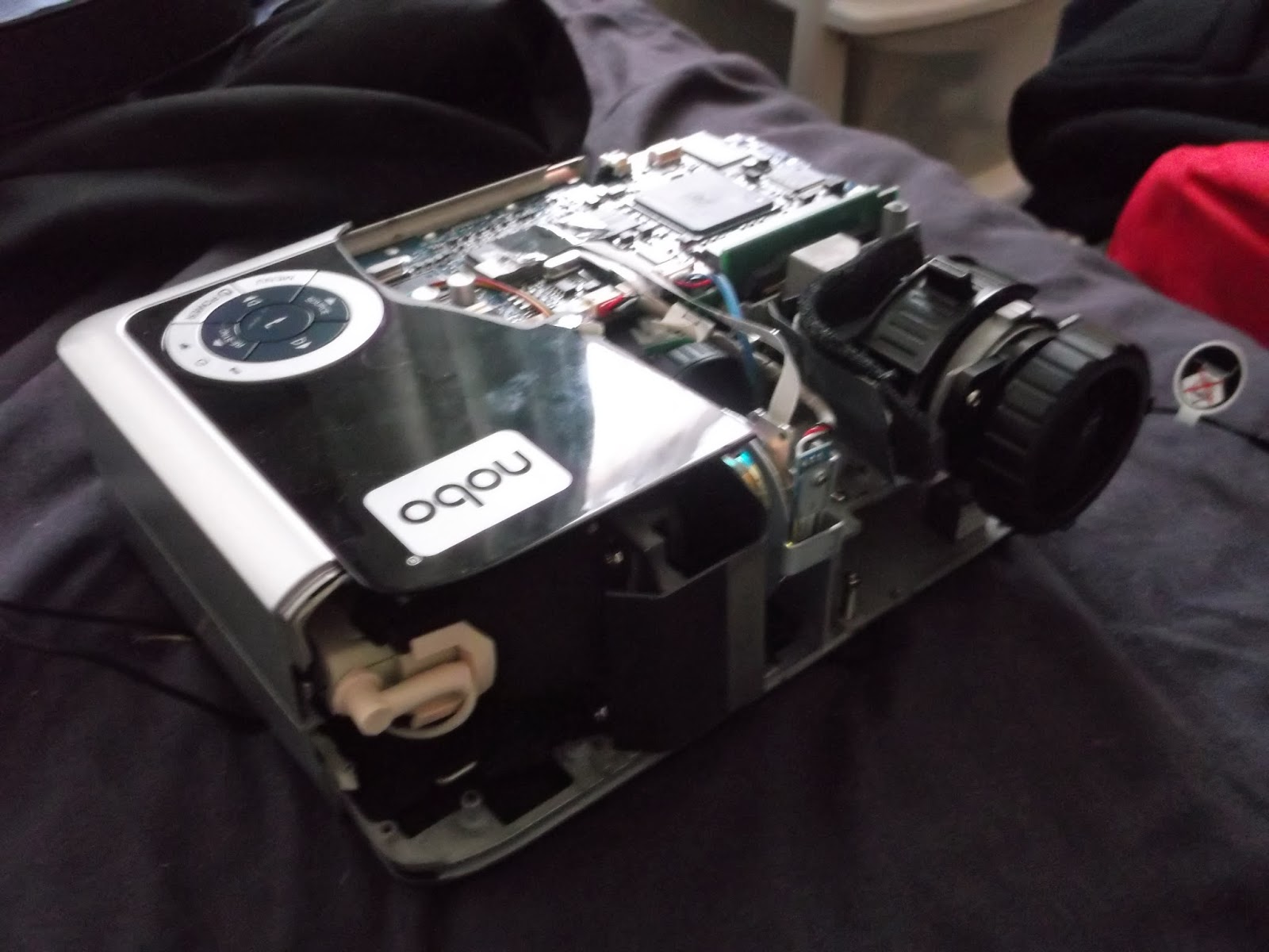
Turns out there was an embedded screw in the middle >:(
That was my attempt to disassemble the unit - you can hardly blame me when it contains more screws than the Titanic's rivet count but it wasn't all for nought:
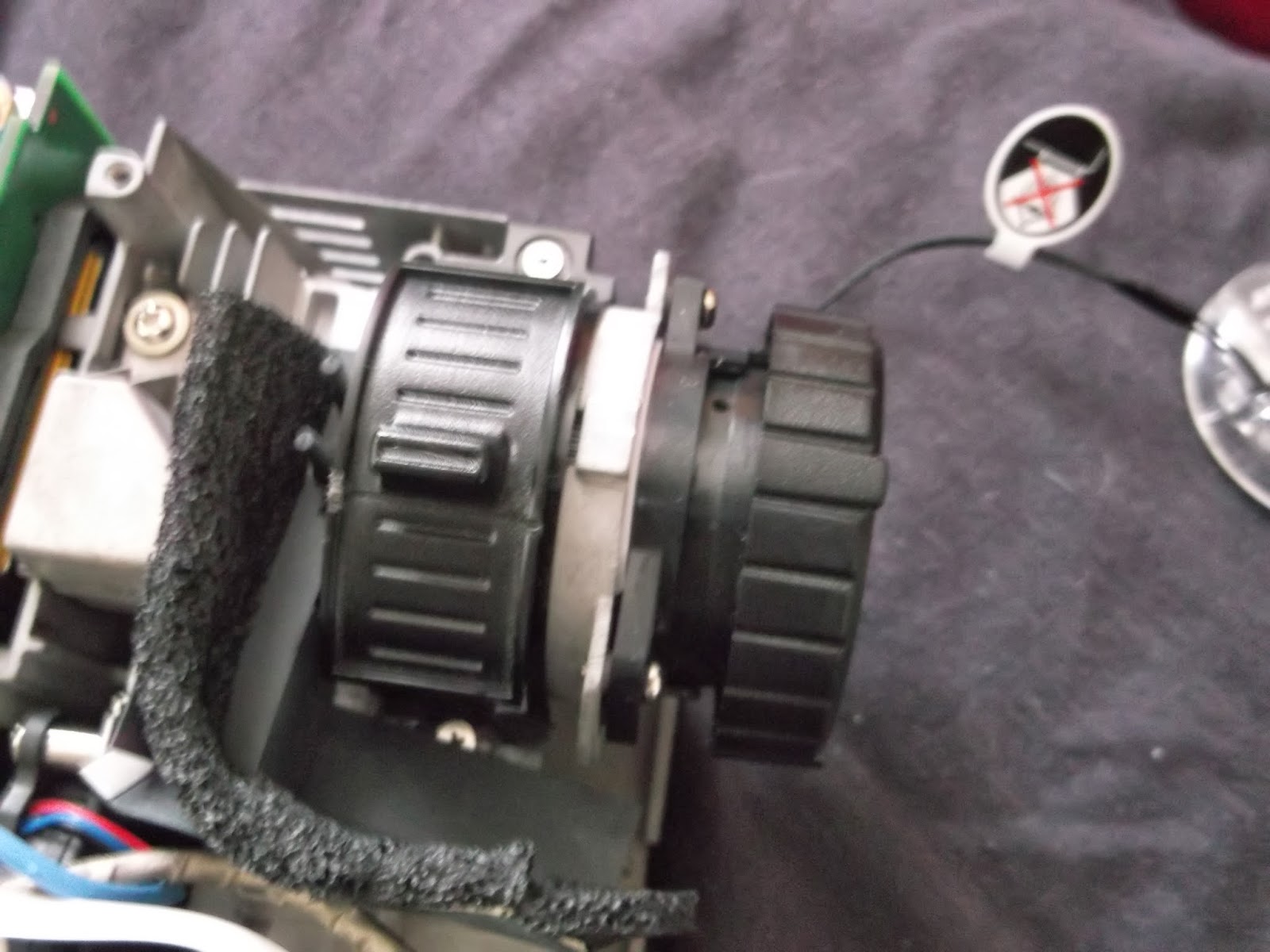
The focusing lens and the zoom lens exposed.
I discovered that you could undo a screw and set the focusing lens free, enabling focus at smaller screen sizes.  I also attempted to free up the zoom lens by sawing away at the slider but that was mechanically limited from going further.  Now I can get a focused image at 12.8cm x 8.0cm without a magnifying glass, and with the addition of a spacer where the lens is screwed in 6.4cm x 4.0cm will be possible.

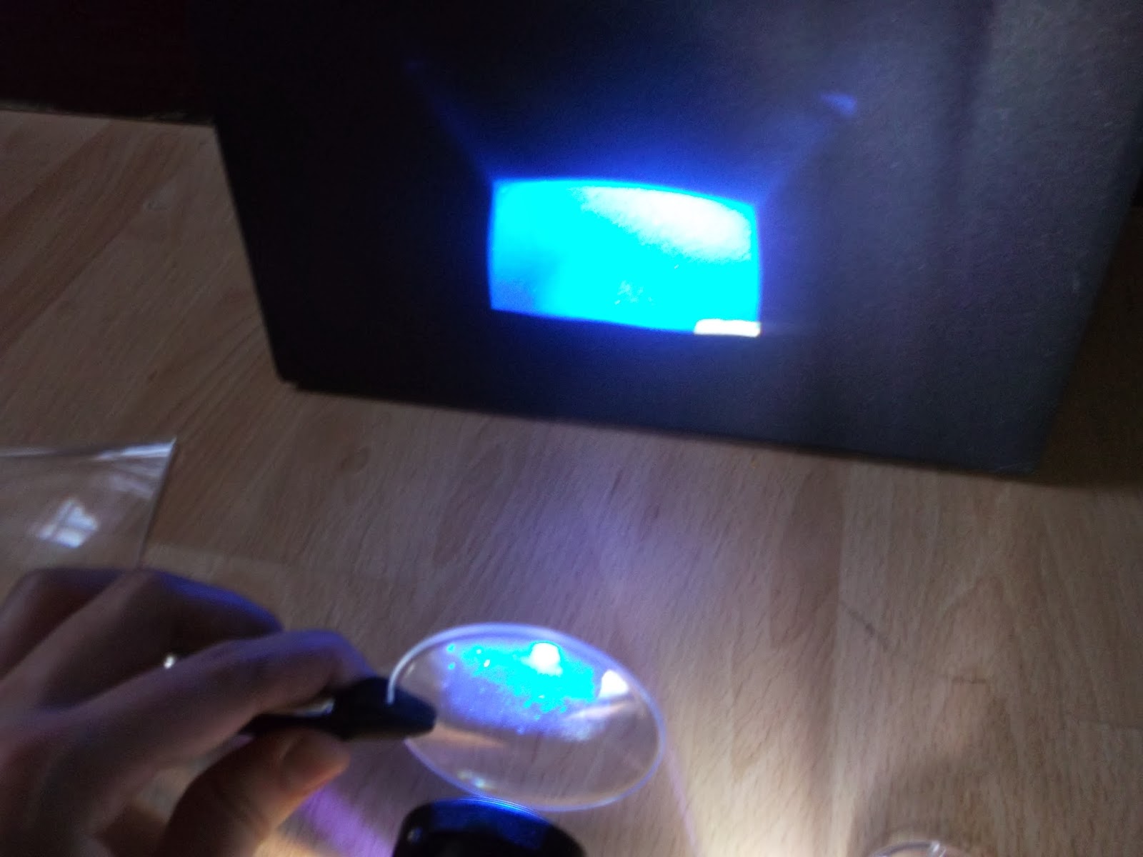
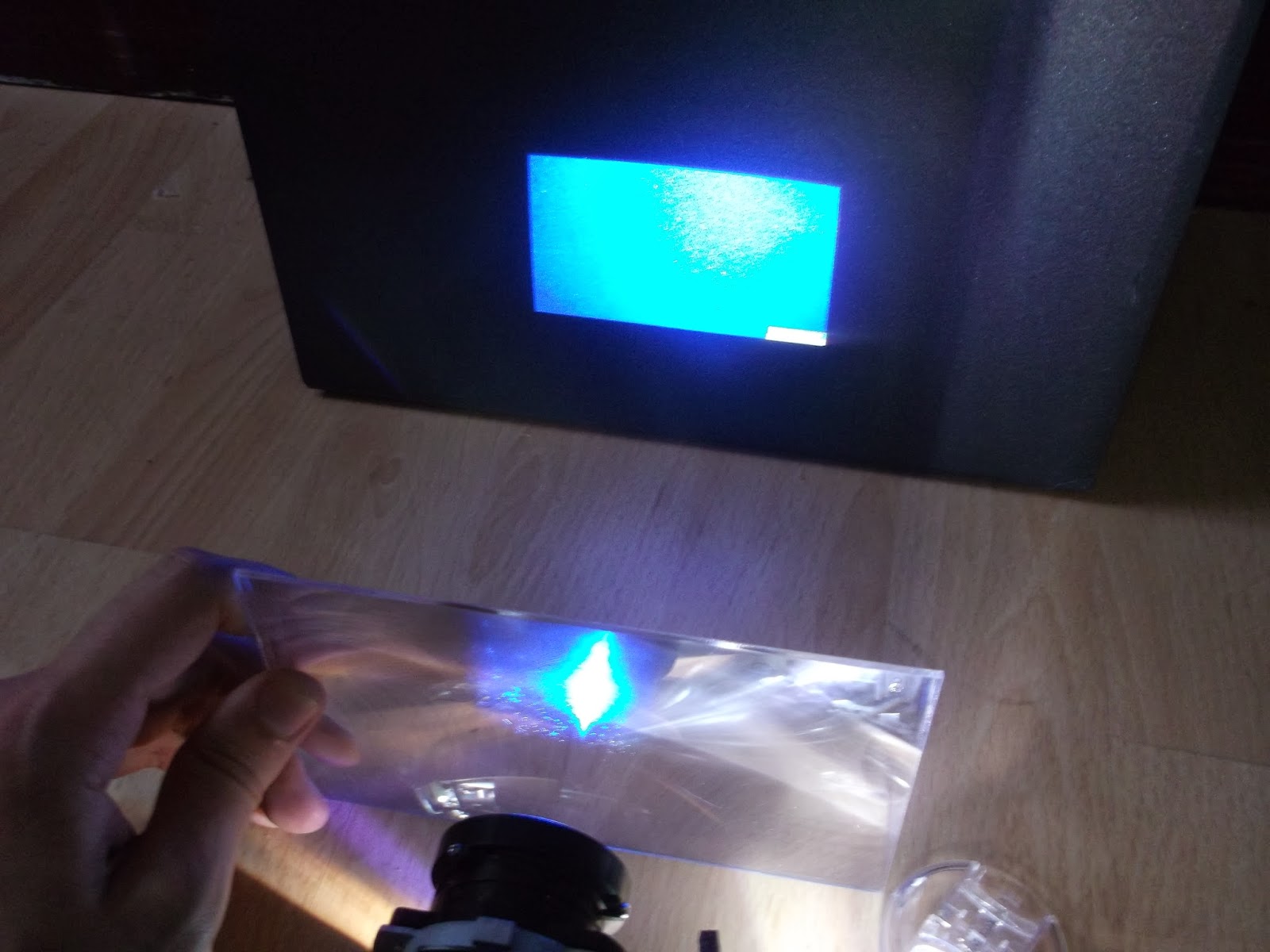
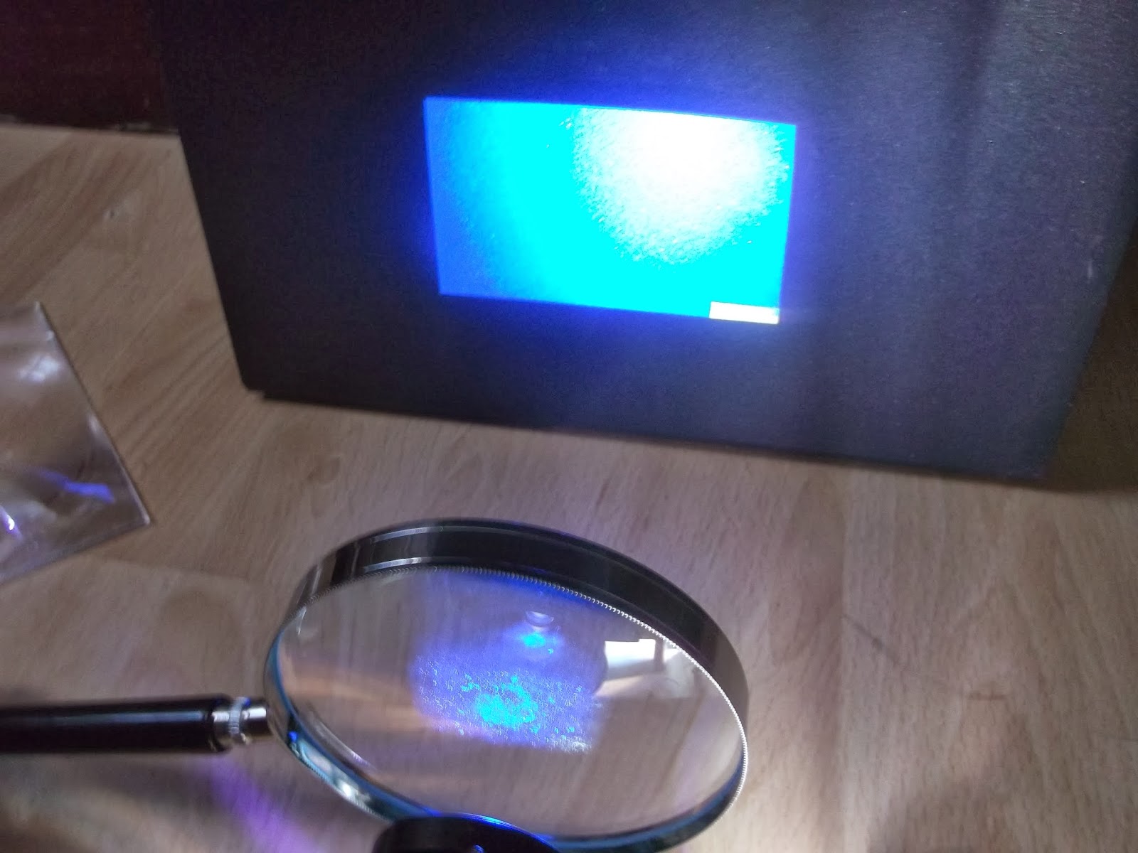
I say that I'll need no magnifying glass because I decided to ditch the expensive DSLR lens (which probably wouldn't have worked) and play with some plain old magnifying glasses.  The aim was to allow an unmodified projector to achieve smaller focused images, thus potentially saving hundreds to experimental makers.  Being as efficient as I am, I'll parade some images of the results:
This 60mm magnifying glass sparked my interest in this experiment, it proved too small for a complete image.
This glass dispensed with the rims, but had poor optical properties; all that was achieved was interesting image distortions.
Fresnel lens, used in reverse:  Almost, but not quite.
Fresnel Lens, used correctly:  Actually made things worse!
Quality 100mm Glass:  Actually proved best overall, but still some distortion evident towards the top - I couldn't source any glasses bigger than this.
As you can probably gather, what was needed was absolutely NO distortion of any kind, for the sake of accurate, consistent printing.  I believe that this is down to the image being set into the correct shape by the focusing lens, thus when another lens comes into the picture, the image bends inconsistently due to differing angles across the projection.  It seems that if you want to use a cheaper projector and still get tiny prints, or make a more expensive model work even better at such, you may need a tool kit and leave those gorilla hands at bay.

When I did get the projector to focus, I managed to assess it's ability to cure resin using an old Gü pot as a container, I am using Spot-GP from Spot A Materials, and the results are decent to say as much as I can at this stage:
This shard is about 1mm thick on average, and It took around 10 seconds to form, so a 0.1mm layer takes a second.
As far as properties go, it's slightly more flexible than FUD from Shapeways, looks a bit like frozen urine and it closely represents FUD in most respects.  I only sort-of pointed the glass at the projector so ripples were to be expected.

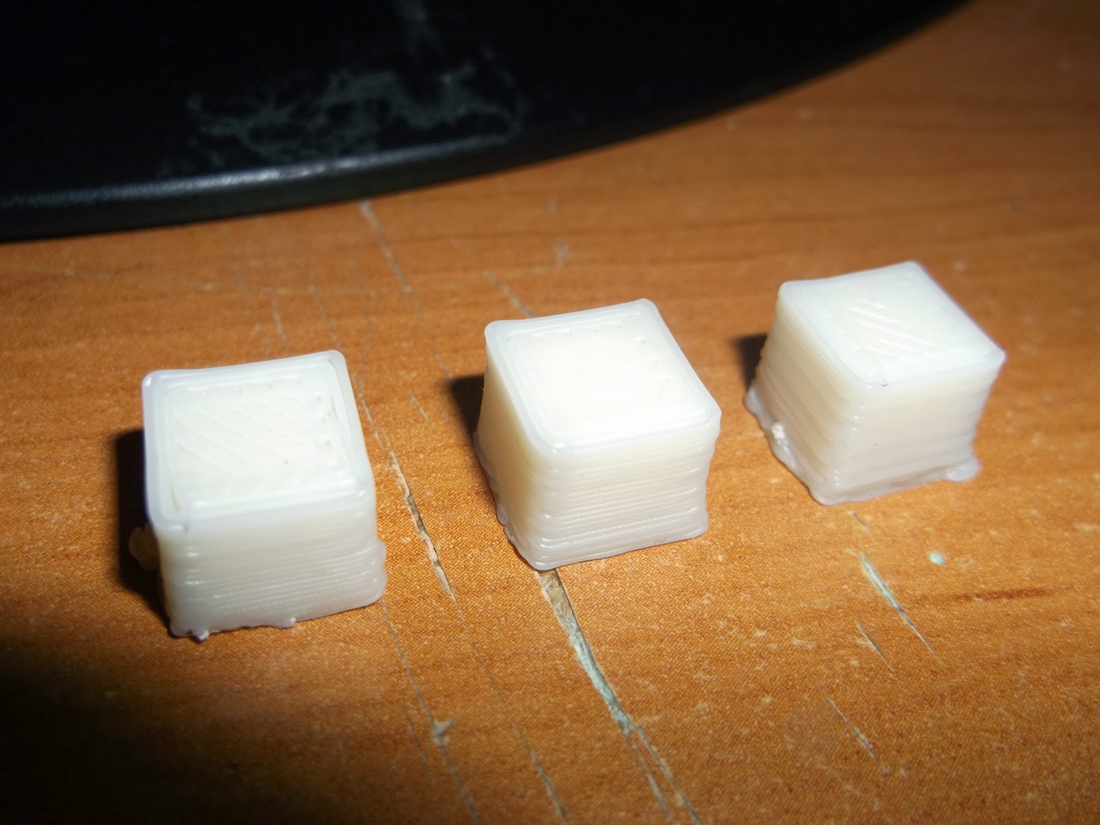
Don't get me wrong, I have reservations about using these resin models structurally, so I have made progress on my Reprap Prusa Mendel i2 in aid of this; before the RAMPS board died (that'll teach me to buy down to a price) I managed to print a few 10mm cubes:
Left:  First successful print, 1mm short in Z, layers haven't bound properly.
Middle:  2nd Print, better, but X and Y axes differ and still 1mm short.
Right:  Best print yet, layers bind and X/Y ratio is 1, but still 9mm in Z.
I could never have guessed that calibrating Z in an FDM machine would be so hard - bed-leveling is bad enough, but I never want to touch the Z endstop again, ever.  It does give me an idea, though:  I could integrate the Z endstop into either the extruder or the bed in future builds, mount it via a nut/bot arrangement to allow fine adjustment as well as add a spring to alleviate backlash in the threads.  The Reprap is pretty much built, however, so it's a bit late to add that; guess I just have to get a monk patch from hair loss...

One final topic:  I've been investigating the onboard computer idea, and some guy called Torben Mogensen is creating a Pi-based controller for his printer.  This is still very much in beta, so I'll go via the simpler but more power-intensive route of adding an x86 PC to the case, which will run Creation Workshop.  I've liberated a PSU from my Main PC from an upgrade, a 700w model that should power all inside without trouble:
That tangle of cables concerns me...
That 700w is spread across 4 12V rails at 18A each, which may add up to 864w but the maximum concurrent draw is 700w.  This'll make things difficult but not impossible, 700w could power the projector as well if I had the confidence to disconnect the Power Supply from it.  Anyway, I have 2 outlines for the built-in PC:

Bespoke AMD Machine:


  • CPU = AMD A6-6400K Dual Core 3.9GHz with Radeon 8470D Graphics
  • Motherboard = MSI A78M-E35
  • RAM = 4GB DDR3 1866MHz to boost APU Graphics
  • SSD = Crucial V300 120GB

Shop-Floor-Bits Machine:

  • CPU = Intel Pentium E2160 1.80GHz Dual Core
  • Motherboard = MSI G41M-P33
  • RAM = 4GB Corsair Vengeance DDR2 1066MHz
  • GPU = Nvidia Geforce 6600GT 256MB
  • SSD = Crucial V300 120GB

The Bespoke Machine costs up to £260 with all ancillaries accounted for, while the Shop-Floor-Bits Machine will only cost £130 in the same condition.  Looking up performance figures on Passmark (great site), I get the following predictions for performance:
  • Format = Bespoke : SFB (% Difference, positive towards Bespoke)
  • CPU = 2400 : 996 (141% more)
  • GPU = 526 : 103 (411% more)
CPU is not so important as GPU performance in this case, since it will need to handle complex STLs in preview without slowing to a crawl.  The AMD system is only twice as much yet has 2.4X the CPU power and 5.1x the GPU power.  I've discovered that creation workshop will slice in seconds even on relatively slow CPUs like my decrepit 2.2GHz Turion TL-64 laptop.  The AMD system is more power efficient too, with a 65w TDP vs 65W+35W (CPU+GPU), or 100W.  The SSD is there for durability and speed, and the RAM is just enough for a smooth OS (probably Windows 7).

Thank you for reading this far, this was a big post and one I put off for quite a while, searching for a Graduate Engineering Job and prepping for interviews is a project in itself.  I'll see you next time, hopefully with some renders for the printer framework.