Thursday 27 November 2014

SLA 3D Printer Project Log 11: Lasing on a sunny afternoon...

Exciting news on the making front:  my Laser Cuts have arrived!  Before I've even finished cutting my Extrusions (I'm a horrendous procrastinator), CutLaserCut of London have furnished me with 6mm Plywood Panels for the exterior; These parts have an almost psychotic precision to them - I drew these in Sketchup which draws Circles as slightly smooth polygons, and every face was sharply defined on even the smallest curves, running my finger over them felt like a D20 would if you felt it with your foot.

I reckon on a little show 'n' tell:

Clockwise from left:  Rear panel with PC Case and 180mm fan in place, Top Panel, Bottom Panel.
As you can see I stuck to fairly simple shapes for this, with lots of holes for the M4 bolts holding the panels on.

Left:  Front Panel; Right:  Both Side Panels (they're identical)
The Oblong bevelled holes are for the access panels which are to be made out of Fluorescent Acrylic (these absorb UV light, cuts out light pollution from external sources).

Another shot of the rear panel with rear-mounted equipment in place.
Of course, the fans will be internal and behind fan grilles once I assemble this thing, but the PC will remain external for access and cooling.

Misc Accessories, parts which make up things like the build bed (bottom left) and the Z carriage upper plate (top right).
The only problem I can see so far is the fact that many of the panels have warped, as can be expected for such thin plywood panels of this size.  It doesn't matter for parts other than the Z Carriage and possibly the Top Vent Cover (the rectangular plate with curved corners and all the cut-outs in), so I think I'll use Aluminium Angle bolted to the Carriage to ensure a level fixture for the Bearings and Threaded Rods driving the Z Carriage up and down.

"Why not use more plywood, or just glue on some Straight Scrap wood?"  Wood has a fantastic Strength-Weight ratio, especially Plywood, but ultimately while it can be very stiff, it is not that strong overall; The parts I use to stiffen can also warp which takes me back to my original problem.

Whew, an enticing delivery indeed, a glimpse into the future form of my Printer; just to end it on a high note, let us view this ultra-cute image of my bodged projector perched on it's mounting plate:

So far I've logged more hours watching youtube videos on this thing than it would be used for roughly 100 small prints!
Stay Industrious.

Thursday 16 October 2014

SLA 3D Printer Project Log 10.5: 12 hours in a single shift? Count me in!

Late July?  What kind of excuse do you suspect I have this time?  I mean, 2.3 months, okay, that's not too bad, I thought it was at least 6 months for some reason.  There is a reason why the Tawe TMD blog has suddenly come back to life (hopefully not to fall dead again), and bizarrely it has nothing to do with model trains.

Let me introduce you to my working life; Before recently I was working a standard 5-day 8-hour week, "Big Deal!" you crow, "I manage to model!", trouble is that I'm quite the lazy git - me and go-getting just don't gel.  The company I work at (not named because legal blah) has been quite demanding with regards to overtime, I usually ended up doing 4 hours on Sunday; Add that to my gym session, an essential as I approach that dreaded mid-twenties period where you apparently balloon up without warning, and I am left with only one free day - Saturday.

Now, if some of those who know me suggest "well, if you let go of them train trips you keep taking all the goddamn time..." they'd have an irritatingly condescending point; I take these trips as though I'd go mental if I stop, I don't even know how I can afford anything else sometimes.

This brings me neatly to 4 on 4 off - this is where you take 4 12-hour days in succession in exchange for 4 consecutive free days.  A quick cliff-note version of my verdict:  Super!  The 12 hour days might sound arduous to some, and they are when there's nothing to do and you are basically being paid not to have fun at home, but overall they only feel marginally longer than 8 hours due to sheer momentum.

"But don't you feel super-knackered afterwards?"  That is true, when I cycle home I feel as though I'm being fuelled by raw desire to slump into bed, but that was also true of 8 hour days and even of 4 hour days when I worked retail or even as a gardener (Sewer Maintenance looks like an adventure compared to those two).  You just exist in a state of semi-cryostasis in which you can only find energy to procrastinate.

Is this a SLA log or not?  Content, dammit!


Yep, this is instalment 10.5 simply because I've not got much new to announce, just a milestone and a minor announcement, really.

I've begun construction!

What industry and a wrecked elbow looks like.

Looks like a sizeable pile of parts, no?  Tell you the truth, I have nearly 15 metres worth of extrusion to cut!  Its all spread out across 11 1.5m extrusions (a decision I rather regret now), and initially I used a junior hacksaw i.e:  a one way ticket to both carpal tunnel syndrome and a dislocated elbow.  Get an Angle Grinder on the Case!

Fittings are yet to arrive, as I've ordered 75 Corner Braces alone, it's not easy for Proto-Pic to fulfil such demands as mine on a dime.  Overall, I seem to be well on my way, a fantastic feeling once you've cleared that dreadful middle part of any project, that pit in the bell curve where energy goes to die.

Minor Announcement?  Oh yeah, I plan to make a free build guide for anyone wishing to make their own machine, I believe that I've already said that the .skp file and .STLs will also be open source.  This, if anything, is a dry run for how I take to writing future build guides and possibly eBooks in future.  I dunno what those'll be about yet, probably train trips.

Stay Superb.

Sunday 27 July 2014

SLA 3D Printer Project Log 10: It's Extrusive!

Aluminium Extrusions...  How could I have missed you so?  Such a simple way to build up frames, especially for prototypes; here I was about to spend £400 on laser cutting plywood into a rigid frame, as well as £160 for 3D Printed parts!

Advertising my stupidity is a good way to begin a post, no?  Just to prove the opposite, I'll divulge to you what I've got in mind thus far:

A fairly basic crate :)
As can probably be seen in this image alone, Aluminium Extrusions are essentially the Lego of the garage hacker, allowing rapid construction of non-standard frames and sub-assemblies by way of nuts which fit into grooves in aluminium bars, with bolts then holding it all together.  Compared to the previous laser-cut plywood design...  Actually, why not invoke an excuse to use bullet points rather than actually write?

Goods

  • Rapid addition of any newly-required features
  • The Projector Crane can be an integral part of the frame for additional strength
  • Plywood parts can be cut by hand - superb precision is no longer needed since it is automatically attained by a precision-manufactured metal framework

Bads

  • If a casing is used (as you can see, it is), you may have trouble upgrading to a bigger projector
  • Design is largely limited to right-angles
Not much on the bad side, eh?  Pity it's far from finished - the build-bed requires extensive re-working since I plan to only use laser-cutting for the Resin Basin (this part needs to be made so well you'd think I cast it whole) and I need to model all the brackets I'll need to assemble this thing.  All in all, not bad for a rediscovery made possible by a discussion with a colleague at work :)

Until we meet again...

Sunday 6 July 2014

How to reduce STL errors: Get your 3D Printed items error free for Shapeways

We've all been here, red faces flagging up all over our models thwarting our attempts to produce consistently printable models.  Just to emphasize how annoying this can get, here is a screenshot of my Caswell Flats STL just after export from Google Sketchup:

Just you wait until you introduce curves into the model...

See those red areas?  Those are degenerate faces, and they can do much more besides making the model unsightly, up to and including causing a non-manifold model - all 3D printers require the model to be "watertight" or manifold to print, that means there must be one consistent shell.

Having gained much practice in handling STL files, usually through frustration, I thought I'd put it to use by outlining these three tips to flush out the degenerates and, better yet, prevent them from happening in the first place:

1.  Get Netfabb


Let's face it, computers being computers, no CAD program is ever going to produce a perfectly error-free *and* a detailed, high-resolution model first time (even if such a program did exist, the cost would be horrendous); enter Netfabb - a slick, attractive application that makes light work of banishing the reds.  The Basic version is free to download and use with no time limits, and it fixes most errors with automatic ease; it is, however, limited to the most basic of STL sins and cannot, for instance, Wrap Part Surface which reconstructs the shell of a model to close up the holes.  For £200 you can upgrade to Netfabb Private, which allows access to all the tools you'll ever need to fix STLs (I personally cannot comment on their effectiveness since I only use basic, still, one for the future investments list).  There is a hideously-priced Professional version costing 1500 Euros, which I'd only suggest if an automatic nesting algorithm sounds vital to you.

2.  Reduce the resolution of your models before exporting to STL


Not a sure-fire fix, but one that can get your models from 'RED ALERT!' to 'that'll do'.  Resolution pops up in many different ways, for instance Creo Elements Direct (which I strongly suggest you get if you want to model curves) features an 'Facet Accuracy' setting, accessed via Right-Clicking the Part, selecting Part Properties, then the Facets tab; This will give the option to set either the minimum distance or angle the model will be permitted to render.  This is the result if I go for the insane resolution of 0.5 degrees:

Aside from bringing my new AMD R9 290 Graphics Card to it's knees, this is what 5244010 triangles and 250mb of Chassis looks like.
So you're thinking it's not too bad, except that 73 shells and 144 holes are produced...  Netfabb ran out of memory trying to fix it (silence...).

Let's go down a gear to 1 Degree and see how it is:

Errors around the Pinpoint bearing holes are reduced :)

The repair I tried in Netfabb Basic did little if anything to reduce those lines, although this exercise illustrates a point:  Reducing the resolution not only rids you of reds, but it also reduces strain on your Graphics Card as it renders the model and it makes smaller files with the 1 Degree file being 67.6mb.

3.  (Sketchup Users) Use Solid Inspector


Sketchup hit the spot for many modellers when it introduced it's extension warehouse, myself included - trawling the internet for obscure, often poorly-optimized plugins is now banished to the past along with floppy disks and those chirpy modem things.  One of these plugins to come to our rescue is Solid Inspector, a straightforward function which highlights any issues with Sketchup models by circling surplus lines with orange and holes with red:

This is a rather severe example, but you can hardly blame us when you take the Tumblehome into account.

That was the body of No. 394 of the Chesham set of Metropolitan Bogie Carriages, at which me and Matt Wickham at Bluebell Model Railway (click here for some video of the carriages running) have been beavering away on for some time; Admittedly finding the actual rogue lines and holes is still tricky since the circles don't always scale to your viewport, but as a general indicator it's a godsend which can mean the difference between printing and self-inflicted pain.

The Takeaway:  3D Printing, not 3D Perplexity


There may well be other methods I have failed to mention, but I can sum this post up thus:  Don't rely on your eyes to find faults.  A CAD model, unlike your hands, CNC machines and even reality, can scale down into infinitude, theoretically to the Planck Length and below; that said, god help you if you want to zoom back out again!

Sunday 29 June 2014

SLA 3D Printer Project Log 9: Call me tight-fisted...

Been almost a god-forsaken month since I last posted on this!  Usual excuses apply - work, tiredness and other priorities.  Regardless of this, I am proud to present a completed model for the SLA 3D Printer!

Mostly Plywood construction to keep 3D Printing costs in check.
As much as I'm tempted to excuse the lack of RAMPs Board and some of the hardware (nuts, for instance), the simple fact is that I couldn't be bothered...
This is where the action is - looking down on the print bed with the beam set to 12.8 x 8.0 cm build area.
With this simple design in mind, let me take you through the DXF files for the laser cutting, which should hopefully let you know just how much goes into things like this:
25346.8mm of lasering goes into the 6mm ply parts ALONE.
Looks refreshingly simpler, but these 12mm ply parts still need 25260.6mm of cutting.
Finally, 12mm Cast Acrylic makes up the basin with a mere 8290.95mm of cuts.
Some of you may be thinking "Gee, that's sure to be expensive with all those finger joints and details" - how does £400 inc VAT sound?  Sure, it's a major expense, but would *you* consider doing this by hand?  All I need to do is persuade my ego to let go of that 4K monitor for just a few more months (not gonna happen ;) )

If you've read this post over at the life blog (to hell with re-writing the name here, that pubescent cacophony of letters needs to change), you may notice that I am aiming for change in the coming months not just with my blogs but my whole life - things are getting quite heavy for me and I need to re-tool.  The basic gist is that I am trying to do too much and it's driving me insane to the point where I just dive into PC Gaming and get nothing done, so a few things may have to come and go.  This project is here to stay (why not cut out the middleman for minor detail/operation changes?), but I'm looking into other avenues to try my hand that may eventually make me a decent living if I can pull it off correctly.

Finally, all my blogging is now on here, (pubescent jumble blog) is now mothballed.  Hope to see grasshopper-minded adventures on a much grander scale once this bridge is crossed.

Stay Industrious...

Saturday 31 May 2014

SLA 3D Printer Project Log 8: Why cut butter with a broadsword? Or alternatively, the AMD Athlon 5350 APU!

Around two weeks ago, I took delivery of a new PC; a machine that is Ivor the Engine to my Gordon of a CAD/Gaming rig and my Edward of a laptop (Peter-Pan Syndrome?  Perhaps...).  This centres around an AMD Athlon 5350 APU, which provides an all-in-one solution to CPU and GPU at least halving power consumption.  The current testing setup is shown below:

I would say that desk space is too mainstream, but I have no desk space ;(

I originally intended for touchscreen operation, sadly the monitor's touch didn't work, neither could I find drivers.  Perhaps a wireless keyboard with built-in touchpad?  Also note the brightness of the projector - that is from a 2200 lumen bulb and the image size is roughly 12.8cm x 8.0cm, or my target print area (the plywood panel is 30.5cm square).

Note the presence of the RAM, or it's stealth capabilities in any case.

Before we move on I just have to sing praises about noise levels - that mini fan on the APU is 50mm across (smaller fans are notorious for noise), yet it can barely be heard with my ears 15cm away.  The fan on the PSU doesn't even spin and I suspect it may not need to given that it's a 300w model and the fan begins at 120w.  Compare that to many budget laptops which can be heard across the room and only feature Celerons and Intel Graphics (for those not in the know, both of those are considered bottom-of-the-barrel).

For the sake of tuning I ran a few tests with the APU running stress-test programs to max out power consumption on both CPU and GPU, varying the Windows power plan each time:

  1. Power Saver:  Idle = 17.0w, Max Load = 36.4w
  2. Balanced:  Idle = 17.6w, Max Load = 36.9w
  3. High Performance:  Idle = 17.5w, Max Load = 36.4w
Astonishment is a perfectly apt way to respond - I know I was!  None of the power plans made any significant difference, and temperature was similarly unaffected:  Idle was around 12 Degrees Celsius (sub-ambient cooling from an HSF?  Black Magic!) while Load topped out at 37 Degrees Celsius.

Idle state on Power Saver (admittedly I replaced the TIM on the cooler with Arctic Silver 5)

Load state on High Performance, with Furmark on the left (the other stress test was Prime95)

So you say "This is stellar news!  But how well does it *actually* work?".  That is a very good question with a compromising answer, in other words, my CAD rig will do a much better job but this will do us well especially given the reduced power consumption - my main rig will sap 150w from the wall at idle!


That gives a crude representation of the UI in action, with an 800x600 resolution (not great) and a highly complex mesh (may be quite common in my line of work, but oh well).  I also managed to get a representation of how the image will look when printing is underway:

That gear was indeed 60mm across, just as designed.

So all in all, a promising start; still have to figure out how to stop the projector from curing resin during start-up or when idle (the desktop extends to the projector in these cases), but I believe this is a much easier and user-friendly solution overall than the Pi even if you suspect I'm being lazy... which I am...

Until duty calls again...

Saturday 3 May 2014

SLA 3D Printer Project Log 7: Underframes? Thought I did those in Creo...

I've been working on underframes, I know, it's a bit soon to resume work on the wagons but I'm on about the mounting system for my 3D printer; until now I had components floating in space - not an ideal proposition for accuracy.  That has now been fixed, and I was in for some wake-up calls.

Don't worry, there'll be 10mm bolts holding the basin in place.
The dimensions were envisioned as a worst-case scenario of 1m3, which would give me plenty of wiggle room to add insane features like gull-wing doors and water-cooling for the built-in pc, but the dimensions as they stand now are 412mm x 380mm x 626mm.  I reckon I can now aim for a desktop model, and this means a few changes:

  • I'll probably ditch the case, and just use a black cover when not in use to prevent the resin from curing - this will probably save me a lot of bother when maintaining my printer.
  • A Mini-ITX PC is essential - I can no longer use the bulk of the unit to house an ATX motherboard.
  • Get more sensible with the design - I (and possibly you) am going to use this printer frequently, I need something serviceable.
  • Mounting the touchscreen just got a lot harder...

A few ancillary developments have happened in my life recently; I've got a new job at a composite manufacturer running cure checks for them, and one of the things I observed is that the Autoclaves run standard PCs alongside their massive built-in computers to run the UI; maybe I shouldn't follow the leader, so to say, but it gives me reassurance that my plan to use an x86 PC to control this thing isn't insane after all.

As much promise as the Pi had, I am not a coder, and Raspbian didn't run how you'd call slick (Risc OS did, but it doesn't support wireless internet which makes things a hell of a lot harder these days); if I'm going to use it everyday, which I may do for a few weeks of each quarter, I'd prefer a rapid system as well as one which has a GUI.

I intend to install Windows 7 Basic to run Creation Workshop by PacManFan, a program which can slice the STLs as well as operate the printer with the help of RAMPS board.  This program uses little CPU power, so the Pentium E2160 I possess can be used (I bought it for a secondary gaming rig, to use whilst home from University), but it does use a lot of GPU power in it's Model View, which runs on OpenGL; I bring up OpenGL because it means that Workstation Cards, designed largely for OpenGL-accelerated CAD programs, could give stellar performance.

I'll expand upon this further when the time comes, I'm getting tired in one of my few windows of time I have to do CAD and blog, in spite of the much-needed money.

Regards.

Saturday 26 April 2014

SLA 3D Printer Project Log 6: The Up of Sketch

Creo Elements Direct is fantastic, it's similarity to Pro/Engineer and Solidworks make it an instant transition for someone in the CAD industry that's used something less archaic than AutoCAD and it basically operates on an Additive/Subtractive modelling principle rather than vertices and points like the free version of Sketchup (Sketchup Pro has Solid Tools which afford the same functionality, but costs $590 or ~£350 at time of writing).  Model Railway wagons are a no-brainer using this method given how many rivets and tumblehomes and other assorted chamfers and blends make it impossible to attain high resolutions under Sketchup.

However, It's use as a design tool for machinery like the SLA 3D Printer Project and the Reprap is severely curtailed by it's lack of visualisation features and it's very modelling system:
Initial design for the Resin Basin, made from 12mm Cast Acrylic.
As can be seen, it's a grey box with a flange, not even remotely looking like the clear acrylic intended for the production model; I also wanted to raise the flange to a level where the top of the flange will be at resin level, allowing me to make a 12mm Calibration Sheet to place in the mount to calibrate the projector - in Sketchup, this is as simple as selecting all faces you want moved, then raising them to the required level, whereas Creo will need you to delete the part, raise the hole locations on the workplanes (all four of them in this case) and then re-extrude the parts.

With this in mind, I have transferred all the geometry to Sketchup by way of drawing them again (I dread having to do this for a locomotive...), and I've made further progress by constructing a prototype for the Print Bed:
I say prototype because I seem to have blocked off the bed to the projector o.O
That's the spot!  Now we can make out which bits are Plywood, which are Acrylic and which are 3D Printed.  I know I ought to have taken the projector into account seeing as it is the most vital part of the machine, but that's okay because it's an iterative process, CAD; furthermore, it is far easier to amend a model than a drawing, which I should know given how small I like to make my concept drawings.

Until next time...

Saturday 19 April 2014

SLA 3D Printer Project Log 6: Quick Snippet

Since the last post, I have been giving thought to my projector mount - long story short, I believe it will be too flimsy with all that weight resting on an 8mm thread (wrt the vertical adjustment).  As a small update while I figure out what to do from here, I have some basic drawings to clue you in on some ideas for two of the Sub-Assemblies:

I don't draw so well...  I'm not the best calligrapher either...
I have now opted for a tighter design utilizing 3D Printed clamps on the 8mm Steel Rods; I can now drastically reduce the distance, and hence the moment arm the projector will enact upon the structure, enabling a smaller frame overall.

Never one for freehand...
This is an initial design for my Build Platform, consisting of a suspended steel grate (a fine pattern to help grip the print) suspended from four LM8UU linear bearings to stabilise the platform, taking moment stresses off of the 8mm threaded rod, which in turn positions the platform.  I have literally just thought of using two motors like the Reprap as long as I can overcome synchronicity issues.

Another thing of note is that I managed to make the Resin Basin in around 30 mins in Creo:
...Which is why I'm a CAD man ;)
So, not a complicated job, simply laser cut from 12mm cast acrylic to allow the use of heavy duty cleaning agents (Extruded Acrylic has microscopic stress marks which the agents can penetrate and cause further damage); the holes in the end and the bottom (not the flanges, I'll cover them later) are sized to take G 1/4" threads commonly used in PC Water Cooling equipment, the one in the bottom drains the tank of all fluids while the side holes act as fill levels for the Salt Water and the Resin on top - Procedure for filling is as follows:

  1. Close the Bottom Valve.
  2. Open the Lower Side Valve (the Upper Side Port will have no valve).
  3. Fill the tank with Salt Water until it flows out the Lower Side Port.
  4. Close the Lower Side Valve.
  5. Fill with resin until it flows out of the Upper Side Port.
A similar procedure is done for draining:
  1. Remove any Prints.
  2. Open the Lower Side Valve.
  3. Let The remaining Resin drain out.
  4. Open the Bottom Valve.
  5. Let the Salt Water drain out.
All fill leveling is therefore done by the tank if the correct procedure is followed, I have it calibrated for 20mm of Resin on top of 110mm of Salt Water, giving 120mm of Z axis Build Area alongside a proposed upgrade of 192mm x 108mm build area once I source a 1080p native projector (once I've sifted through all them "1080p" projectors with an embarrassing native resolution of 800 x 600 >:(  ) .

The other holes on the flanges are simply mounting holes to suit M10 bolts, and another idea as of present is to make a calibration sheet from more 12mm Acrylic set to the same height as the resin to position the projector accurately.  I propose using L plates for accurate positioning of the basin.

Take care :)

Friday 4 April 2014

SLA 3D Printer Project Log 5: 200 Step Program

I've recently obtained a Raspberry Pi (and instantly overclocked it - reached 900MHz CPU, 500MHz GPU and 600MHz RAM with an overvolt of 8), as skeptical as I was at first, this £25 Set-Top Box with pretensions to being a Linux PC is giving me some real inroads in this project.

I've already got it to run a NEMA 17 Stepper Motor through an EasyDriver V4.4, and my coding prowess is as extensive as the Waterloo and City Line; I did this via WiringPi, a library for the Pi that enables you to use the GPIO Pins without using Python or typing sudo (super-user do) ahead of every command.

The commands entered were:
  • gpio mode 1 pwm - this assigns Pin 1 to PWM operation
  • gpio pwm-bal - this enables Balanced PWM, which is SoC default
  • gpio pwmr 100 - this sets the range to 100, or 0.1ms per unit
  • gpio pwm 1 - this sets the duty cycle to 1, or 0.1ms out of 10ms
Keep in mind it is possible I am hideously wrong at this stage, I don't own an oscilloscope and with that in mind I am a cretin.  I frequently used PicoScope in Electronics class in College so that'll be my first port of call.  I believe I also need to vary the frequency to change the speed, not the duty cycle; maybe that'll need a dedicated board...

In other news I have finished my Projector Mount for the SLA 3D Printer, images below:
Frontal View, the width of the frame (sans handles) is 580mm.
Isometric View.
Rear view, showing the main frame.
A side-on shot showing the guts of the traverser.
I'm slightly doubtful about the 8mm steel rods I'm using to support a Projector which may weigh up to 5kg, so let's do a few Beam Bending Equations :P

Let's assume that the projector is positioned dead centre of the supporting rods in both axes, and that it weighs 5kg, it's centre of mass is spot-on in the middle of the Traverse Plate and 100mm above it (to account for an early, heavy and highly bulky DLP projector).  These are the crucial dimensions (for moment calculations):

  • Horizontal Rods are 560mm long, so 280mm is the moment arm
  • Vertical Rods are 565.5mm long, gives a moment arm of 282.75mm
  • There is 62mm from the Horizontal Rods to the Traverse Plate
  • This falls to 13mm with respect to the Vertical Rods
  • On the Traverse Plate there is 170mm between the centres of the bearings (for the vertical axis)
  • 317mm is the distance between the Horizontal Bearings
In order to find the deflection (which will cause uneven projection distance and hence ruin our prints), we need to find the moment arms and hence the force experienced by the beams at their various points; we know the Mass of the Projector is 5kg, this multiplied by 9.81m/s2 gives us 49.05N of force, which for the sake of simplicity we will disregard for the vertical axis for now, and focus on it's effect on the horizontal axis.

Mooching around on the internet found me these highly useful formulae:
Thanks to Andy Ruina of Cornell University for this PDF so I didn't have to format this pile of symbols
The formula at the end is of greatest interest to us, and the symbols are as follows:
  • P = the deflecting force:  what we are hunting for
  • l = the length of the beam in question
  • E = Young's (Elastic) Modulus = ~200GPa for Mild Steel
  • I = Second Moment of Area, details below
There are many formulas for the Second Moment of Area, as it's highly dependent on the cross-section of the beam in question:  we'll be using (Pi*r4)/4 since that corresponds to a solid cylinder.  Our cylinders are 4mm in radius so (3.14*0.0044)/4 = 2.011x10⁻¹⁰ m, there being two rods so double that to 4.021x10⁻¹⁰ m4

With this information gathered, we can deduce that the denominator of this fraction is 48*200,000,000,000*4.021x10-10 = 3860.39 GPa.m4 (Dimensions will be useful later); the numerator will be 49.05*0.5603 = 8.61N.m3, therefore we get a δmax of 0.00223m or 2.23mm down in the centre.  Keep in mind this doesn't take moments into account nor does it account for the bearing spacings.

Wow, this really is looking like 200 steps!  I didn't expect to go back into my university course this soon, but it did highlight the fact that I may need to review my reliance of Reprap-derived mechanisms especially since I don't want my threaded rods to take on an undue amount of mechanical strain.  I'll end it there for today and continue with this lark at some other point, just because I'm tired of entering HTML mode to put in <sup>(Superscript text here)</sup> constantly.  Time for a kip...

Tuesday 1 April 2014

SLA 3D Printer Project Log 4: A projector mount with traversing features, potential as a garden railway traverse table?

Aside from experiments in salt, I have been working on a mounting method for my projector; one which offers versatility both in terms of adjusting projector distance to vary the build area/resolution balance and also to make way for projector upgrades.  Given that I am building a top-down design this is no easy task considering that gravity threatens to either collapse my construction or slowly inch the projector down and out of focus.  So far, this is my design which as of yet only features the vertical axis:
Looks very Reprappish, and that's because it is :D
I am keeping to Reprap parts as much as possible since every 3D printing enthusiast and their Budgie has a Prusa Mendel of some kind, so relevant parts will be cheaper; the central rod is a M8 threaded rod and the other two are 8mm plain steel rods for support and guidance, SCS8UU bearings are used throughout due to their cast metal housing and built-in M4 threads.  Another thing to note is that the Traverse Plate (highlighted in green) is not what will carry the projector - I intend to make another plate bespoke to the mounting requirements of my projector and users can make bespoke mounting plates for their respective projectors.
The bearings for the horizontal guide rods can clearly be seen.
The Backplate may look a bit skeletal for some, but this is made out of 12mm plywood; 6mm plywood may be used to allow for simplification of manufacture with other parts like the Traverse Plate, with 12mm parts made of two 6mm parts epoxied together (this also allows for half-engraved features without half-engraving, which could bring potential de-lamination issues to a single 12mm sheet).  The large amount of space also allows for a high degree of nesting to occur, saving material and space on the laser bed.
Trusses added for stylistic reasons ;)
This is the mounting cross for the Traverse Plate, where the plate interacts with the M8 rod to allow the plate to move vertically; this is done via two M8 nuts located in slots (just visible above), of which one or both may be a nylock nut to provide friction when traversing is not required.  This is made from a 12mm (or 2 x 6mm) plywood cross which interfaces with a 3D printed nut mount to create the mounting cross.
Reprap inspiration is found again...
Finally, we have the clasps for the plain steel rods that guide the Traverse Plate.  Not much to mention here other than it's 3D printed, I've decided to use Shapeways for my prints since it's WSF printers offer almost infinite flexibility in the shape of my objects within reason and my Reprap is giving me constant trouble right now, so much for saving money by printing at home :(

Good news is that design should be straightforward from here, since I only need to replicate the parts I have made here in the horizontal axis with a few minor tweaks.  Pity this is only one of five sub-assemblies I am slated to design (Projector Mount, Resin Basin, Z axis with build plate, the Mounting Frame and the Case).

Saturday 29 March 2014

SLA 3D Printer Project Log 3: Salt and Spot-GP

So I finally got around to conducting an experiment in how much salt is needed per unit volume of water to buoy the 3D resin.  Overall results were:  Flotation, Frustration and Fiery throat...  well not quite, but 3D resin does get it's vapours in there and make it sore.

I filled a measuring jug with 500ml of water and an unspecified quantity of Spot-GP (around 75ml I believe, which in a 14cm x 9cm basin is around 6mm of resin), As before the resin sank to the bottom of the jug:
That's not another menacing fluid in that beer glass, that's Robinson's Orange & Mango.
I then proceeded to add salt in 10g increments, observing the water as it took on a misty opacity and more blobs of Spot-GP found their way up:
Sadly at this point, the blobs would still choose gravity as their mistress...
When I got to 60g of salt, I chose to adopt the more efficient method of weighing the salt bottle, dumping salt in, weighing it again and finding the difference; at 75g the resin was buoyed but over time it took on a form that would doubtless terrify any sea creatures below:
I suspect Archimedes will come in useful when ascertaining salt content for the actual tank.
Once 120g was reached this behaviour ceased, but the resin was still too heavy for my liking, so I added 30g to make 150g and that was my final amount - 1 Litre of water to 300g of salt:
Still have no idea why that step was there...
That isn't a final number - I couldn't test the planned 20mm of resin due to the constraints of the jug and Archimedes states that the force uplifting the less dense fluid is equal to the mass of the denser fluid displaced, thus it becomes easy to calculate the salinity required for a 20mm layer of resin in a 14cm x 9cm basin (with some cheeky help from here):

  • 140mm x 90mm x 20mm = 252,000mm3
  • Water is at 50C to account for exothermic heat from resin curing and summertime conditions.
  • The density of Spot-GP is around 1050kg/m3.
  • Hence the mass of the fluid is 0.2646kg.
  • For the same volume of Saline Water to buoy this resin effectively we need a density of 1200kg/m3.
  • At 50C worst case scenario therefore we need 270g of salt per litre.
  • I plan to allow for up to 150mm of Z travel in my design, so basin depth will likely be 200mm with 180mm of Saline Water, giving a volume of 2,268,000mm3 which requires 612g of salt.
While this amount may be alarming, it shouldn't hit the wallet too hard since salt costs around 30p for 750g, which is staggering considering 500g of Sylgard 184 costs £50 and to fill the whole tank with Spot-GP will cost a humbling £230 just to fill the tank.

Other observations of note:


  • Cured resin tends to float in the absence of a build plate, which should be good for build quality but presents a challenge for finding a suitable build plate material.
  • The resin stuck well to a stainless steel teaspoon I had on hand (I used a cigarette lighter blue LED to do the curing, 3 cheers for professional equipment), and the part did not loosen even when stirred vigourously through the fluid.
  • Some bubbles of water were present in the resin even after salt was added, so a through mixing may be useful before printing, perhaps with an electric whisk.
  • Some of the salt came to rest at the bottom of the fluid even after stirring, so take that into account when mixing the Saline Solution.
  • Natural UV light pollution from the room cured some of the resin around the edges of the jug (image below), so a "Dark-Box" will be necessary and the printer cannot be open-frame.
Quite a day today, especially since I did some science for once!  To cap it off, here are two ancillary images from the experiment:
A clear ring of resin is to be seen, there's another one at the bottom if you look closely.
Two of the test "Prints" done via blue LED.

Wednesday 12 March 2014

Spot GP and Salt... literally, that's the premise of this post...

I am pleased to announce that I have achieved success in getting Spot GP resin to float on saltwater; I have no idea how much it took, my first attempts with a "reasonable" amount of salt made my heart sink:
This is what I get for being reasonable.
However, a further heap of salt produced this:
Spot on, Spot GP :)
In related news, I've recently come across the Noble 3D Printer project, which gives a build area of 270mm X 200mm X 400mm (x,y,z), or way above Reprap Specifications; using a 1080p projector gives a minimum resolution of 0.185mm in the Y axis, half of the Reprap's 0.35mm minimum recommended nozzle size.  Kinda makes me want to up sticks, but then I saw the requirement for a welding kit - I aim to make my printer constructable without any welding, I didn't mention that before.  I plan to use plywood sections as the framework and outer shell.

At any rate, it proves the idea of using a saline solution to float the resin - and save hundreds - is entirely workable, I need to buy my own supply of salt (my parents like chips as much as I do) and a measuring jug to conduct a proper experiment to attain an actual ratio, so that'll be the next topic.

Friday 7 March 2014

SLA 3D Printer Project Log 2: Nemesis = Norovirus

You know what needs to die in pain?  Norovirus.

I attended Brighton Modelworld 2014 on Saturday the 22nd of February (such was the state of my affairs afterwards, took me long enough), all went fine until the return train ride (Brighton - Clapham Junction - Farnborough Main) that I suddenly felt a great heave in my belly...  and up came some grapes...

Two hefty, debilitating vomits later, you have the longest and tensest train rides you can ever experience.

So yep, I have no idea why this Demon-spawn (of which as few as 5 can infect) isn't on the CDC's hit-list, but that's why I've taken so long to get back on track; and what better to kick it off than a projector that has seen better days:
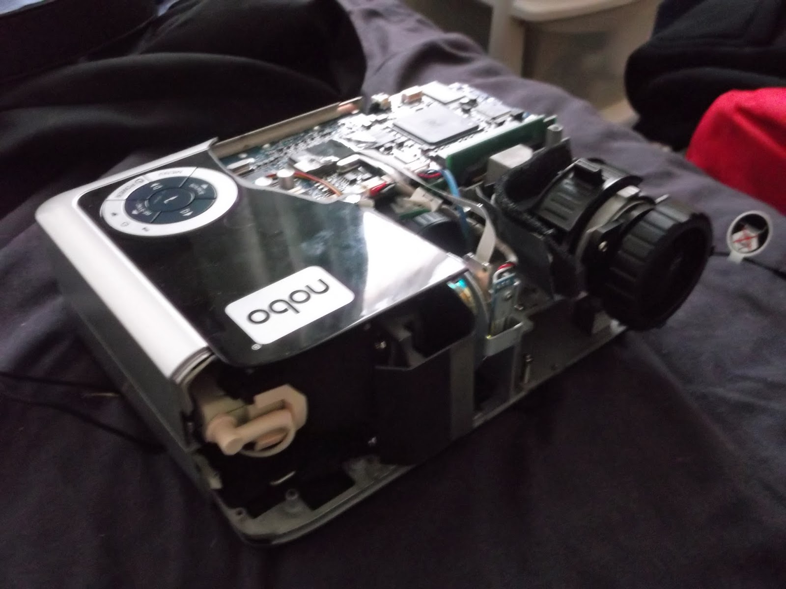
Turns out there was an embedded screw in the middle >:(
That was my attempt to disassemble the unit - you can hardly blame me when it contains more screws than the Titanic's rivet count but it wasn't all for nought:
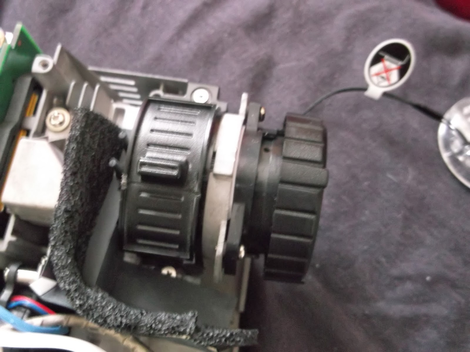
The focusing lens and the zoom lens exposed.
I discovered that you could undo a screw and set the focusing lens free, enabling focus at smaller screen sizes.  I also attempted to free up the zoom lens by sawing away at the slider but that was mechanically limited from going further.  Now I can get a focused image at 12.8cm x 8.0cm without a magnifying glass, and with the addition of a spacer where the lens is screwed in 6.4cm x 4.0cm will be possible.

I say that I'll need no magnifying glass because I decided to ditch the expensive DSLR lens (which probably wouldn't have worked) and play with some plain old magnifying glasses.  The aim was to allow an unmodified projector to achieve smaller focused images, thus potentially saving hundreds to experimental makers.  Being as efficient as I am, I'll parade some images of the results:
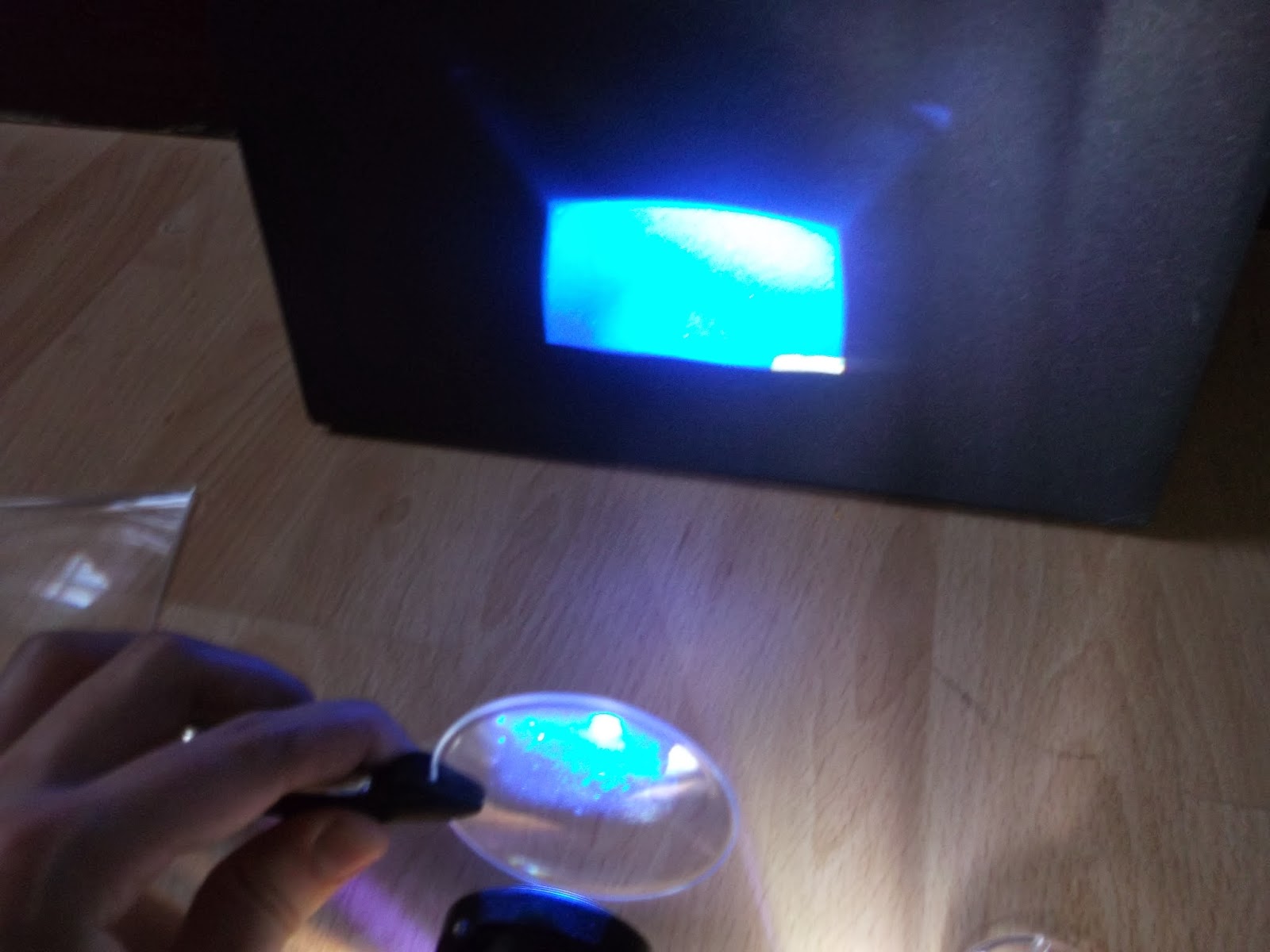
This 60mm magnifying glass sparked my interest in this experiment, it proved too small for a complete image.
This glass dispensed with the rims, but had poor optical properties; all that was achieved was interesting image distortions.
Fresnel lens, used in reverse:  Almost, but not quite.
Fresnel Lens, used correctly:  Actually made things worse!
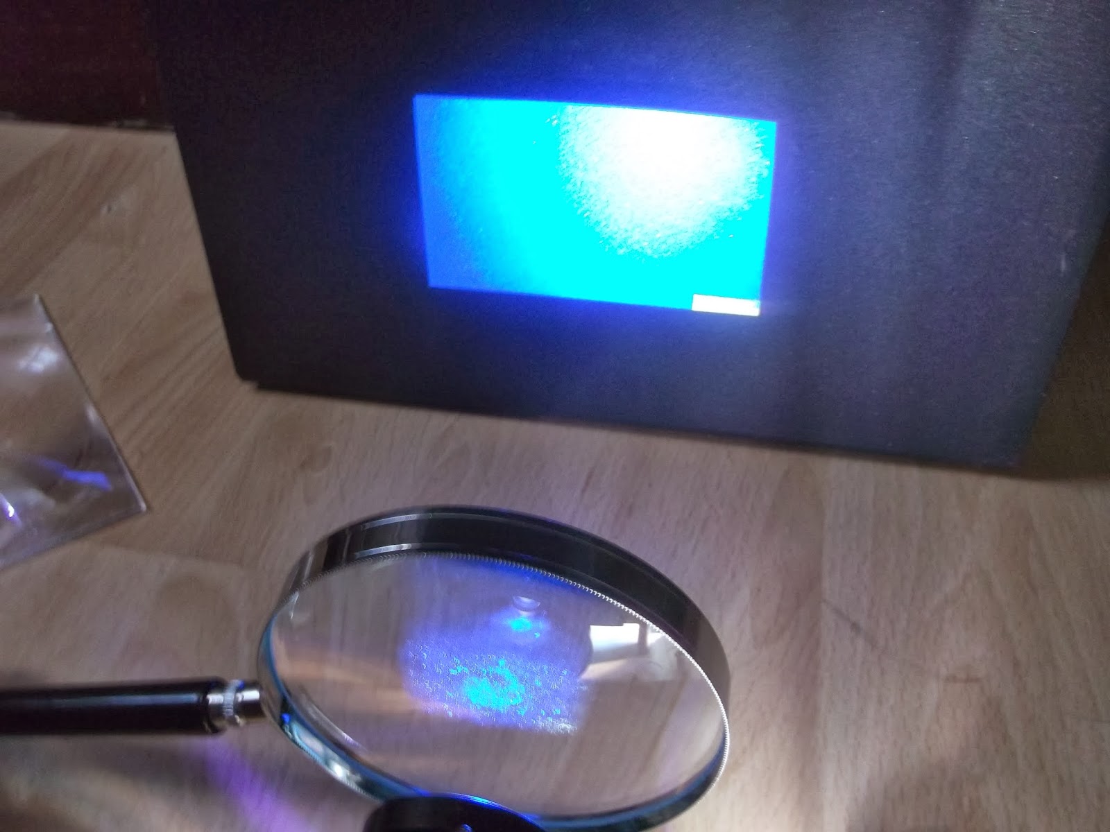
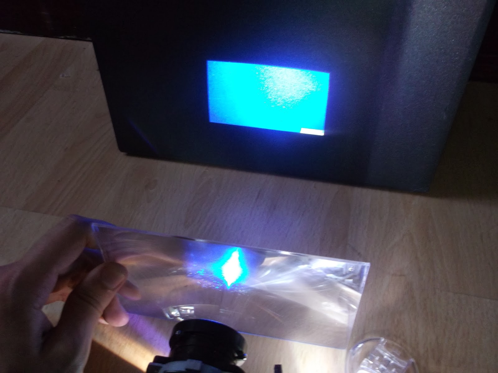
Quality 100mm Glass:  Actually proved best overall, but still some distortion evident towards the top - I couldn't source any glasses bigger than this.
As you can probably gather, what was needed was absolutely NO distortion of any kind, for the sake of accurate, consistent printing.  I believe that this is down to the image being set into the correct shape by the focusing lens, thus when another lens comes into the picture, the image bends inconsistently due to differing angles across the projection.  It seems that if you want to use a cheaper projector and still get tiny prints, or make a more expensive model work even better at such, you may need a tool kit and leave those gorilla hands at bay.

When I did get the projector to focus, I managed to assess it's ability to cure resin using an old Gü pot as a container, I am using Spot-GP from Spot A Materials, and the results are decent to say as much as I can at this stage:
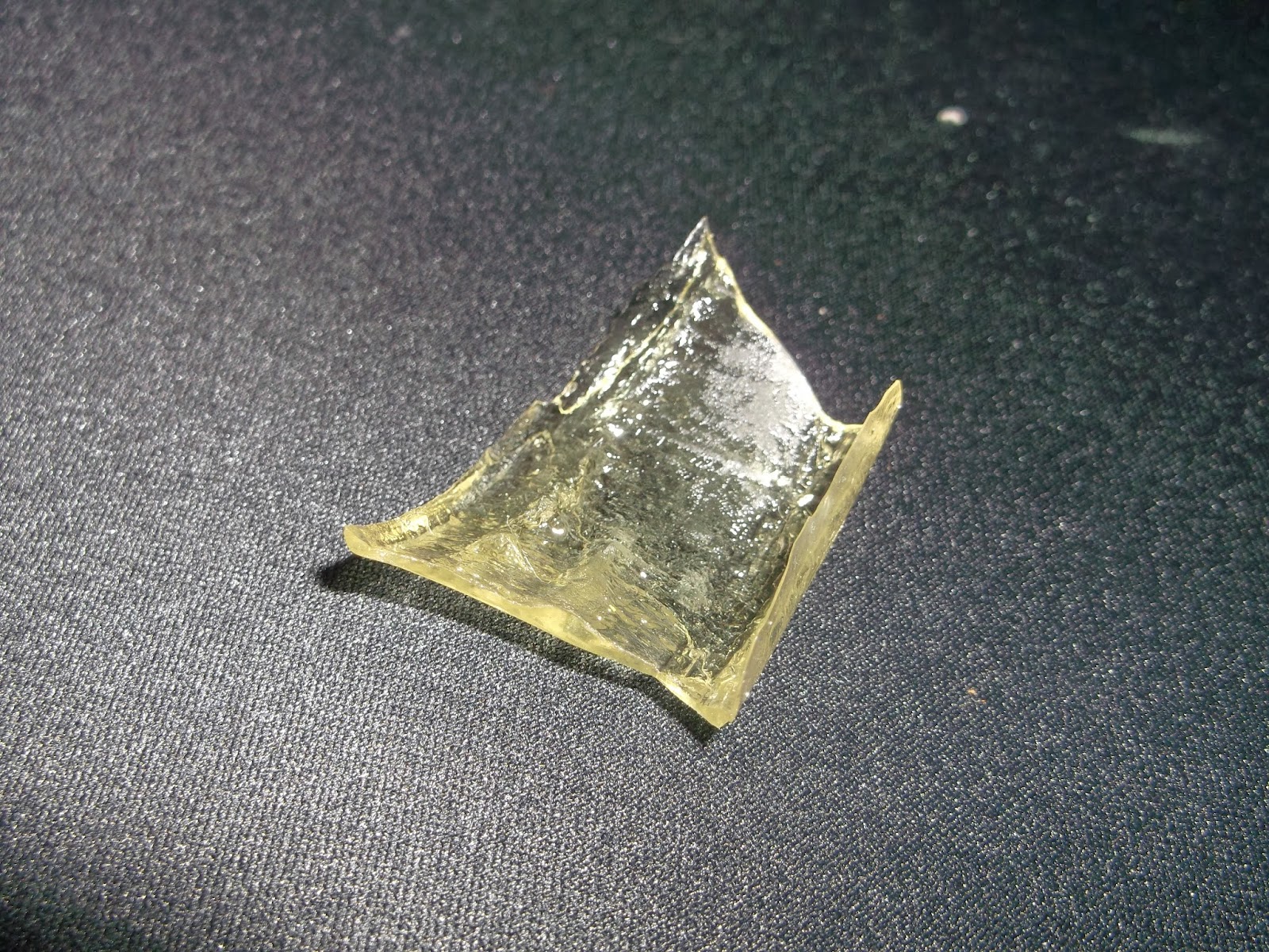
This shard is about 1mm thick on average, and It took around 10 seconds to form, so a 0.1mm layer takes a second.
As far as properties go, it's slightly more flexible than FUD from Shapeways, looks a bit like frozen urine and it closely represents FUD in most respects.  I only sort-of pointed the glass at the projector so ripples were to be expected.

Don't get me wrong, I have reservations about using these resin models structurally, so I have made progress on my Reprap Prusa Mendel i2 in aid of this; before the RAMPS board died (that'll teach me to buy down to a price) I managed to print a few 10mm cubes:
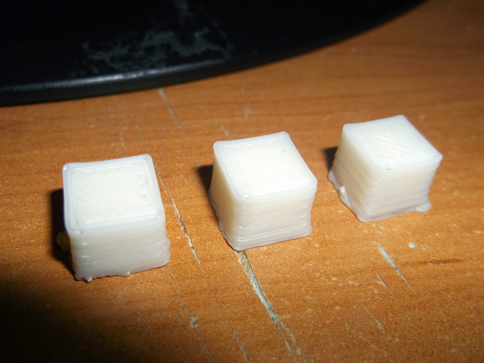
Left:  First successful print, 1mm short in Z, layers haven't bound properly.
Middle:  2nd Print, better, but X and Y axes differ and still 1mm short.
Right:  Best print yet, layers bind and X/Y ratio is 1, but still 9mm in Z.
I could never have guessed that calibrating Z in an FDM machine would be so hard - bed-leveling is bad enough, but I never want to touch the Z endstop again, ever.  It does give me an idea, though:  I could integrate the Z endstop into either the extruder or the bed in future builds, mount it via a nut/bot arrangement to allow fine adjustment as well as add a spring to alleviate backlash in the threads.  The Reprap is pretty much built, however, so it's a bit late to add that; guess I just have to get a monk patch from hair loss...

One final topic:  I've been investigating the onboard computer idea, and some guy called Torben Mogensen is creating a Pi-based controller for his printer.  This is still very much in beta, so I'll go via the simpler but more power-intensive route of adding an x86 PC to the case, which will run Creation Workshop.  I've liberated a PSU from my Main PC from an upgrade, a 700w model that should power all inside without trouble:
That tangle of cables concerns me...
That 700w is spread across 4 12V rails at 18A each, which may add up to 864w but the maximum concurrent draw is 700w.  This'll make things difficult but not impossible, 700w could power the projector as well if I had the confidence to disconnect the Power Supply from it.  Anyway, I have 2 outlines for the built-in PC:

Bespoke AMD Machine:


  • CPU = AMD A6-6400K Dual Core 3.9GHz with Radeon 8470D Graphics
  • Motherboard = MSI A78M-E35
  • RAM = 4GB DDR3 1866MHz to boost APU Graphics
  • SSD = Crucial V300 120GB

Shop-Floor-Bits Machine:

  • CPU = Intel Pentium E2160 1.80GHz Dual Core
  • Motherboard = MSI G41M-P33
  • RAM = 4GB Corsair Vengeance DDR2 1066MHz
  • GPU = Nvidia Geforce 6600GT 256MB
  • SSD = Crucial V300 120GB

The Bespoke Machine costs up to £260 with all ancillaries accounted for, while the Shop-Floor-Bits Machine will only cost £130 in the same condition.  Looking up performance figures on Passmark (great site), I get the following predictions for performance:
  • Format = Bespoke : SFB (% Difference, positive towards Bespoke)
  • CPU = 2400 : 996 (141% more)
  • GPU = 526 : 103 (411% more)
CPU is not so important as GPU performance in this case, since it will need to handle complex STLs in preview without slowing to a crawl.  The AMD system is only twice as much yet has 2.4X the CPU power and 5.1x the GPU power.  I've discovered that creation workshop will slice in seconds even on relatively slow CPUs like my decrepit 2.2GHz Turion TL-64 laptop.  The AMD system is more power efficient too, with a 65w TDP vs 65W+35W (CPU+GPU), or 100W.  The SSD is there for durability and speed, and the RAM is just enough for a smooth OS (probably Windows 7).

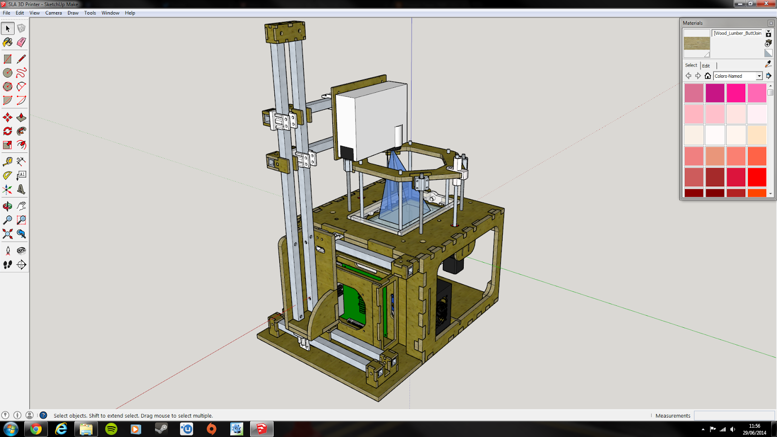
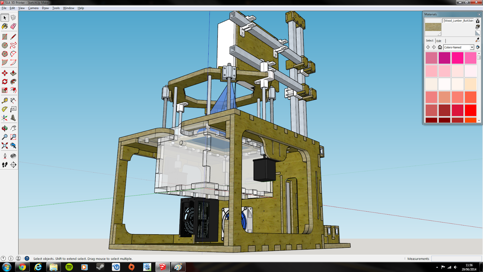
Thank you for reading this far, this was a big post and one I put off for quite a while, searching for a Graduate Engineering Job and prepping for interviews is a project in itself.  I'll see you next time, hopefully with some renders for the printer framework.